NET acquisition data
Dewesoft NET application module provides nice way to acquire data over the network. This allows to use multiple systems as one instrument or to acquire data from different locations.
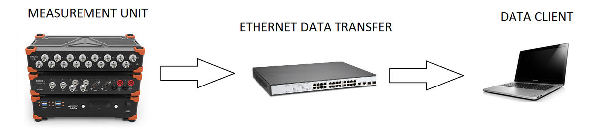
Dewesoft NET application module allows one or more measurement units (named MU’s) to be under the control of other computers, named CLIENTS. The MU(s) and CLIENT(S) must be connected via TCP/IP.
Work with Dewesoft-NET composes three basic procedures (steps):
- NET Setup Network configurations, appropriate hardware and Dewesoft-NET setup
- Measurement - Manage measurement units with NET menu option including Measure transfer speed; Creating a display, measure-acquire data and store this data on net
- Analyse Analyse acquired and stored data on net, export measured data
Modes of operation
Dewesoft NET offers three modes of operation. With these three modes, almost any application can be covered. From single channel expansion over remote control to distributed measurements over hundreds of kilometers - everything is possible.
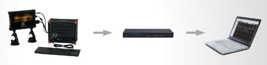
1:1 mode - Single measurement unit and single client
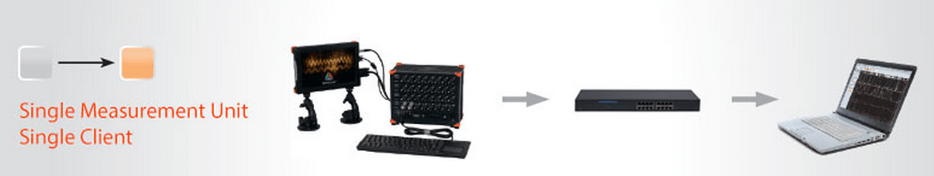
1:1 mode works with a single measurement unit and a single client. In this mode, there are two types of operation: full remote control and data view only. In full remote control, the client computer acts like a master of the measurement system. When the master client changes to the setup screen, the measurement unit also changes the setup screen.
However, in the “view only” mode, the measurement unit acquires data, while the client computer can connect to it and view the “live” data, but it can’t control the measurement unit. A “view client” can look, but not touch.
x:1 mode - Multiple measurement units and single client
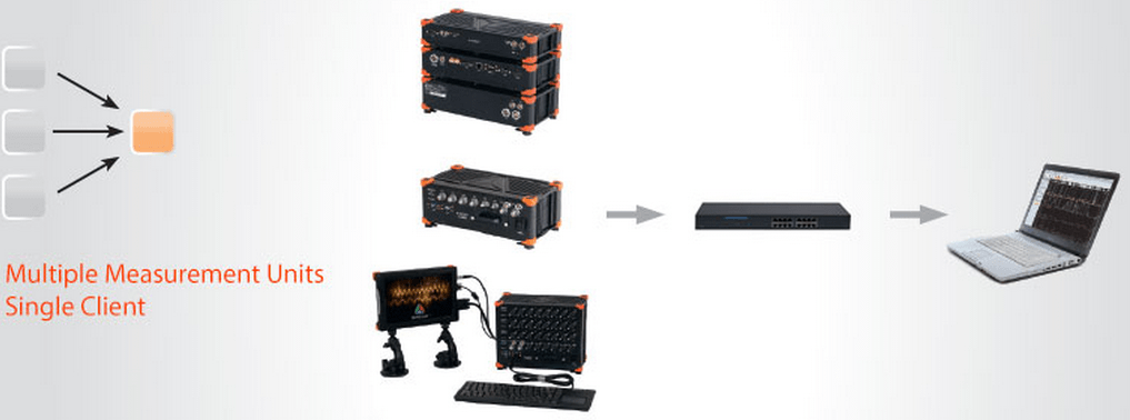
Multiple measurement units and a single client are used in the case of distributed measurements or too high acquisition rates to be managed by a single measurement unit. The measurement units have to be synchronized either with hardware clock (one unit is the clock master, the others are slaves) or with the external clock source that is either IRIG or GPS.
All measurement units can run with different acquisition rates, in this case, only one connection option is possible - the client is always the master. It starts and stops the measurement on all units in the measurement network. At any time, the client has access to view mode - but only to one measurement system (one-to-one connection like in a single measurement system & single client configuration). Additional view devices are possible, but they can access only a single measurement system.
1:x mode - Single measurement unit and multiple clients
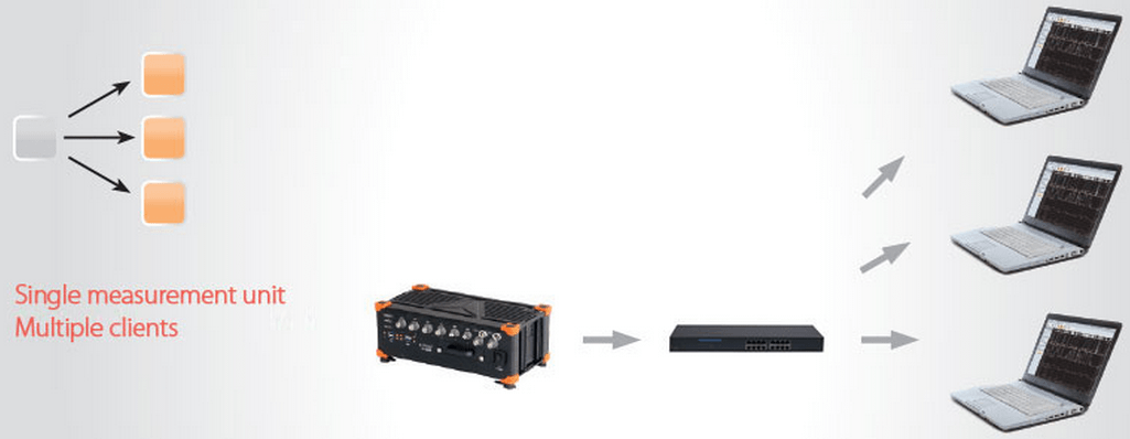
The third network configuration is to have a single measurement unit controlled by one ‘master’ client and additional ‘view’ clients. The master client is able to change the measurement system setup, storing strategy, start and stop measurements, and much more. The view clients are only allowed to receive data from selected channels from the measurement unit (up to the bandwidth limitation) and view and store the data on their local hard disk.
x:x mode - Multiple measurement units and multiple clients
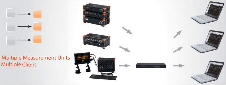
This configuration is used in large scale measurement systems where data storage is an important factor considering the huge number of channels, the high sampling rate, and the systems where the data is stored. The acquired data can be separately stored and processed on several clients.
- NOTE: The view clients are only allowed to receive data from selected channels from the measurement unit (up to the bandwidth limitation) and view and store the data on their local hard disk.
Time synchronization between the data acquisition systems is established with synchronization cables. The measurement units have to be synchronized either with internal hardware clock (one unit is the clock master, the others are slaves) or with the external clock source that is either IRIG or GPS.
Sampling rate can be set differently for each measurement unit. In this configuration one master client is needed. Other clients are in view/slave mode - it is only possible to receive data from selected channels from the measurement unit and access the stored data.
Types of connections
The NET system is always connected via Ethernet protocol. This can be obtained in several different ways:
- Point to point connection (It is the easiest and most simple configuration of the NET system. On either side, you have a computer (S-box, Minitaur, PC, laptop, …) with a measurement device (DEWE-43, Sirius, …) or without it. Point to point connection means, that we have an Ethernet cable between those two devices. With this connection, you have to manually set the IP addresses on both sides.)
- Through router
- Through local network LAN. Wired/Wireless. The limitation is the connection speed.
- Through the internet. Wired/Wireless. Dedicated TCP/IP ports needs to be opened
Point to point connection
With the point to point connection, we connect two devices with the Ethernet cable. We just have to manually set the IP addresses on both sides.
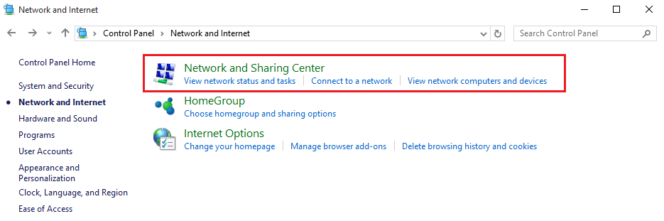
In order to do that, we have to go to Control panel - Network and Internet - Network and sharing center.
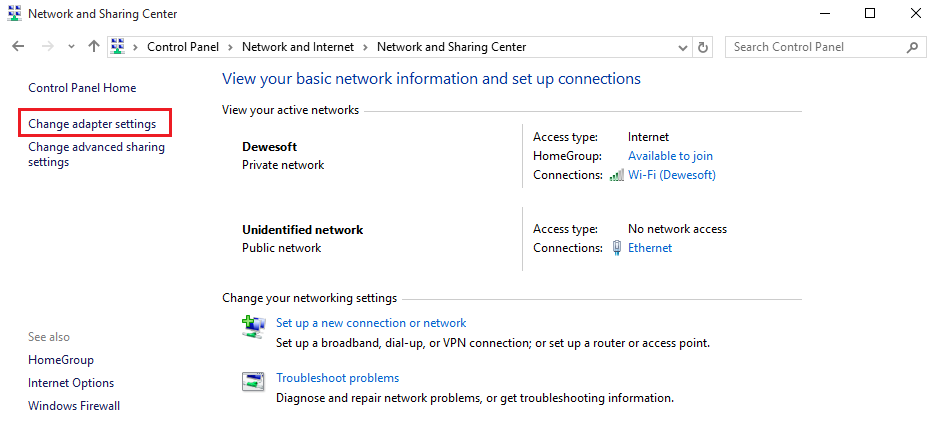
 We need to select Change adapter settings.
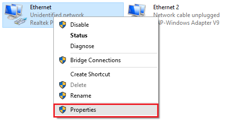
Right click on Local connections and select the Properties
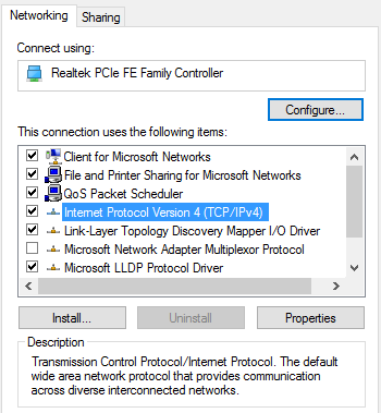
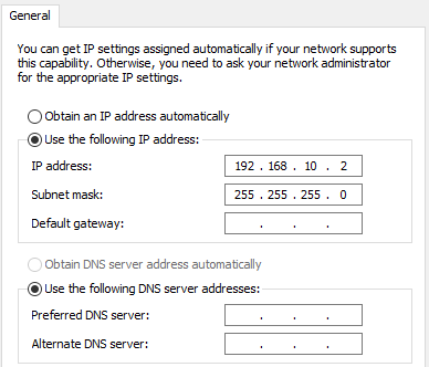
In Properties, we choose Internet protocol Version 4 (TCP/IPv4) and type in the IP address.
IP addresses on devices must be the same, except for the last number, which must be different (ex. IP address on the first device 192.168.10.1 and the IP address on the second device is 192.168.10.2)
Now we can connect with the device, measure and collect data from it.
Connection through the internet
The underlying chapter describe on how to connect two or more more DewesoftX instances that are on different locations and unable to connect physically to a network. Since Dewesoft NET requires that instances are in the same network we will utilize open source solution to connecting them to the same VNC server.
For demonstration purposes we will use Zero Tier provider which is open source. You can arbitrarily use any other provider applicable to your needs. In the underlying chapters we will show only important steps of configuration.
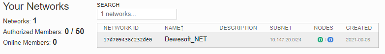
First step is to create a new account and register to the ZeroTier account to access your admin console. This will allow you to create your own network and 16-digit network ID to which you will be able to connect with each DewesoftX instance. When you’re logged in to the web service press “Create A Network” icon and define a name. Other parameters are filled automatically so you don’t need to define them.
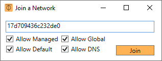
After successfully creating the network, click on the Download tab on Zero Tier and intall ZeroTier on each DewesoftX instance to get a unique 10-digit node. When installation is done run the ZeroTier One App. The yellow icon will appear on the bottom right corner where you should right-click on it and “Join Network …” . Following this enter the 16-digit network ID from ZeroTier Console into the join network field on the PC to request to your network.
When you press Join wait for a while and you will see that new instance wants to connect in the web console. You should verify the connection of each instance as shown in the picture below. Please note, that you can also see assigned IPs for each connected DewesoftX instance which you will be able to onnect through Dewesoft NET.
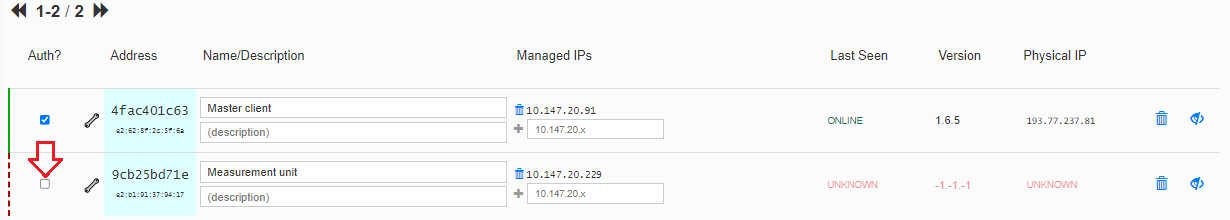
To be sure that instances see each other you should use “ping IP_address” command in Command Prompt. Dedicated IP of instance is under “Manager IPs” column.
For further steps on how to establish Dewesoft NET between DewesoftX instances you can use the manual of Point to point connection. Anyhow, below are a few steps you need to follow:
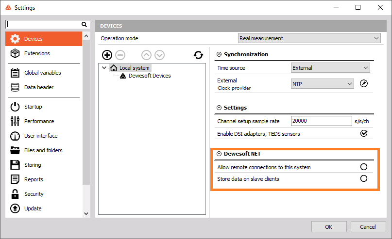
- Enable “Allow remote connections to this system” in DewesoftX Settings
- When connecting to the remote instance use the IP which you will see in the ZeroTier console under “Manager IPs”. Please refer to the above picture.
- Synchronize the instances either with GPS or NTP
NOTE: For the demonstration purpose we used open source VPN server which is located on unknown location. For higher bandwidth performance we recommend establishing a server which is located at the middle of DewesoftX instances as much as possible.
Measurement unit configuration
There are several possible configurations and setups:
- Standalone unit – not networked to anything (the default setting of Dewesoft upon installation)
- Slave measuring unit – can measure data under either local control or under the control of a master client
- Master measuring unit – can both measure data and control other measurement units (optional)
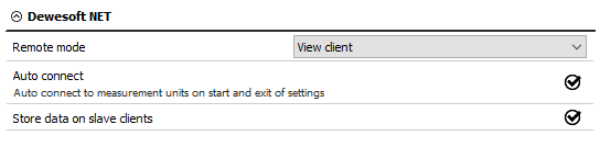
- View client – can view data being recorded on the measurement units, but cannot control them
- Master client – can control the measurement unit(s) and view their data
Each measurement unit must be configured as a slave measuring unit in order to utilize the Dewesoft NET software – however, if you are going to use one of your measurement units as the controller for the others, then you should configure that one unit as a master measuring unit.
It is not possible to have more than one “master” within a single Dewesoft NET system, in order to avoid confusion and conflicts.
Difference between Master/View/Slave client in NET system
- Master client: Can control the measurement unit(s) and view their data.
The Master client is able to change the measurement system setup, storing strategy, start and stop measurements, and much more.
The Master client completely controls the inferior measurement unit - when the master unit switches to the setup screen, also the Slave/View client switches to the setup screen.
In the master client, the “disable mouse and keyboard” checkbox can be used to prevent a local operator from changing any settings on the measurement unit or interfering with the test. With this checked, the measurement unit cannot be operated locally – you will have complete control over the client.
- View client: Can view data being recorded on the measurement units, but cannot control them.
However, in the “view only” mode, the measurement system acquires data, while the Master client computer can connect to it and view the “live” data. But View client can’t control the measuring system. A “view client” can look, but not touch.
The view clients are only allowed to take a few channels from the measurement unit (up to the bandwidth limitation) and view and store the data on their local hard disk.
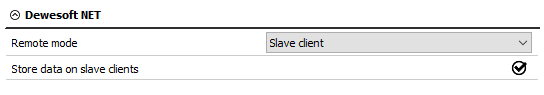
- Slave client “Slave mode” can be selected on the client. Basically, this mode is the same as View client, the only difference is that when the Slave client is selected an additional computer can be connected to the client.
Slave client can measure data under either local control or under the control of a master client, but the master client overwrites all the local storing.
NOTE:
- Master client and View client can be connected to the slave.
- View and Slave can initiate the storing under the condition that the measurement device is in measure mode. And when the Mater client starts the storing other clients will be taken-over and the data will be overwritten.
- To avoid confusion there is recommended that only one Master client is used in the system.
Setup
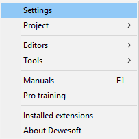
To activate the appropriate mode for each system within the Dewesoft NET, first run Dewesoft. Now click on the Settings menu.
Operation mode must be set to Real measurement. To add new devices click the plus button.
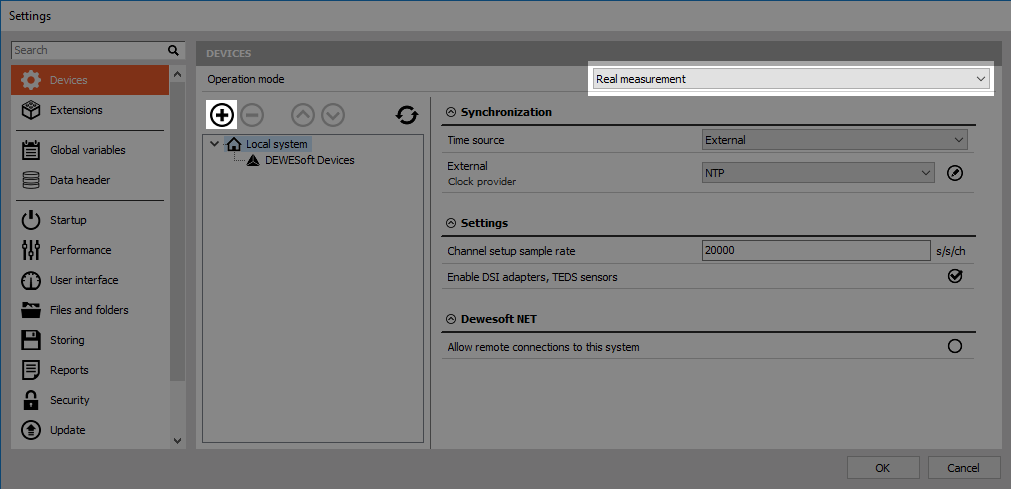
Now you can add new devices. Under Dewesoft NET select to add new Measurement unit.
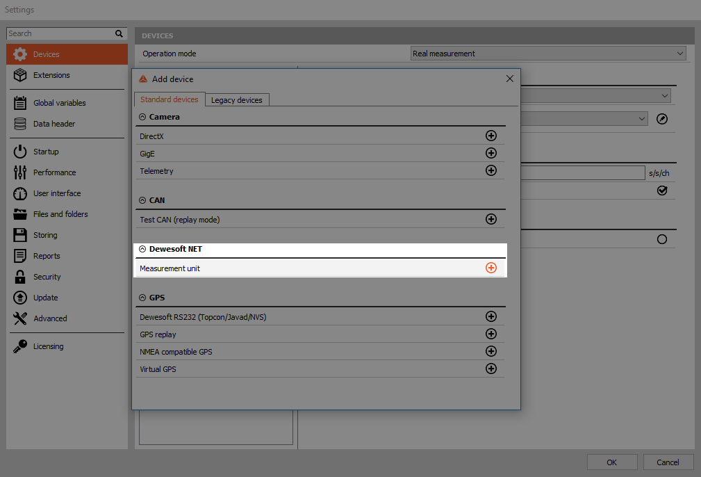
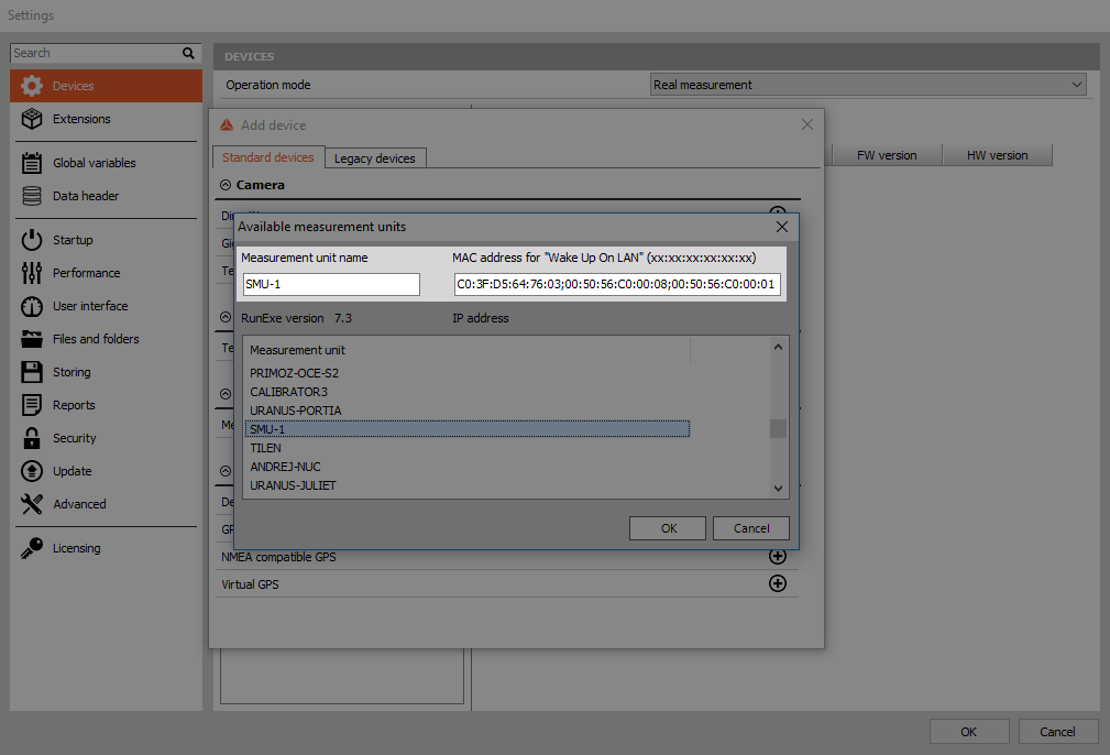
You will see all available measurement units (names, MAC addresses, …).
Dewesoft Launcher must run on measurement devices so that they can be seen as available units.
Principle of Dewesoft NET application module
It is important to note that by default actual data is stored on the measurement units, even though it can be viewed by the clients. This is critical to protect yourself against data loss which might occur by the network going down or transmission being interrupted. Even if this happens, the data is safely stored on the measurement units. When the network connection is reestablished, it is possible to reconnect automatically.
Even if the network going down or transmission was being interrupted, the data is safely stored on the measurement units. The idea of Dewesoft NET technology is to have a distributed system when:
- the required computing power is too high for a single measurement unit (many channels sampled with a high sample rate),
- there is too much distance between the units for analog data transfer,
- the measurement unit is not accessible (dangerous measurements, test rig measurements, …),
- data from measurement units shall be displayed on several client computers,
- measurements have to be remotely controlled or supervised.
Within Dewesoft NET the master client completely controls the slave measurement unit - when the master unit switches to the setup screen, also the slave unit switches to the setup screen.
It is often not possible to transfer all possible channels in real time to the client for storage, even using a gigabit Ethernet interface.
Imagine even one Dewesoft system with 32 channels, being sampled at 200 kB/s each at 24-bit mode. This is already 25.6 MB/sec, which is more than 200 Mb per second (where each Byte = 8 bits). It does not take long for the network to be completely overloaded with data and be overwhelmed with packet loss.
Immediately after the acquisition is stopped, a button appears on the controlling client allowing the data file(s) to be uploaded from the measurement units for viewing on the client computer.
Setting up a master client
In the case where your Dewesoft systems are all slave measurement units, you will need one master client to control them. Let’s assume that we are now sitting at this computer and have Dewesoft properly installed and ready. Click on the Settings menu.
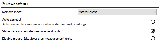
Now use the selector to assign this computer to be the Master client, as shown below:
After confirming the Dewesoft NET setup, the following window will appear:
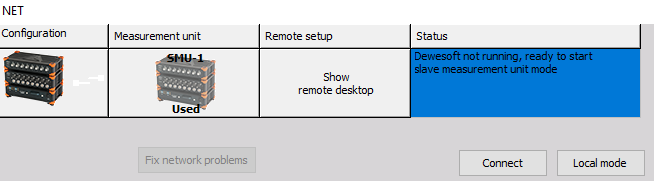
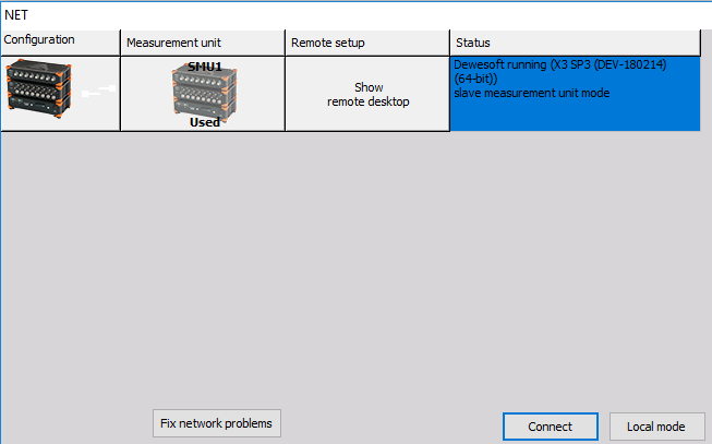
Select the Connect button to connect with the measurement unit.
After successfully connecting, the measurement unit will be seen like in the picture below.
Note that the slave measurement unit called Smu-1 was already found in our example. But if you have not already configured and connected to a measurement unit, just click the Add button and select one or more measurement units in order to add them to the system.
Now click OK to close this dialog and you will notice that the basic Dewesoft screen has a new addition to the top bar – a NET icon:
![]()
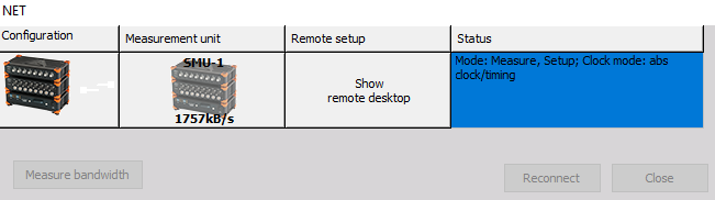
Click on NET icon to show the connection screen. Clicking the Measure bandwidth button in the system will check network performance. In a 100 Mbit network the transfer speed is about 10 MB/second while Gigabit LAN offers speeds close to 100 MB/second. Please note that the real bandwidth is also limited by system performance.
Setting up a Cross trigger
Cross triggers can be used with the Dewsoft NET option in combination with triggered storing (e.g. fast on trigger). The feature allows you to share triggers between different measurement units, therefore enabling measurement unit X to be triggered by a signal acquired on measurement unit Y. Absolute time synchronization (e.g. IRIG-B DC) needs to be used in order to enable this functionality.
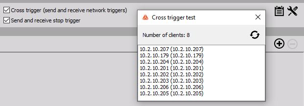
You can activate cross triggers under the Storing options in the Storing module.

For the triggers to work properly you need to configure additional settings that can be accessed by clicking on the tool icon. The proper network interface needs to be selected on each system and all systems need to be in the same Multicast group with an identical IP address. The Cross trigger delay is used in case the network is preoccupied and the “information” from one system to another can be delayed. The default value for the delay is 0.5 s.
If everything is set up correctly you will be able to see a list of all the systems in the same Multicast group by clicking on the list icon.
Measurement
In this section we can see the procedures to control the acquisition by the client:
- creating a display on the client
- storing data on the measurement unit
- transfer stored data to the client
- NET menu option
Creating a display on client
Before you begin storing, you may want to set up the local display. In previous steps, you may have configured the display of one or more measurement units, but you probably want to see data here, too!
You certainly know how to do this. Use the Overview, Scope, Recorder buttons at the top of your own screen here on the Client to create displays with any combination of channels from any and all measurement units!
As mentioned previously, all measurement units must have a SYNC method in place in order to ensure these three things:
- truly synchronized data files from multiple measurement units
- ability to display channels from more than one measurement unit on the client
- ability to create math channels on the client with channels from more than one measurement unit
Note that the CHANNELS list is now showing channels with the “name” of the MU that they come from automatically. This is so that you know the source of every channel in an easy and convenient way.
In our example, the name of the MU, “TESTING-PC” is added in front of the transfer channels from that MU by default.
The channels from each measurement unit will be shown this way automatically. This is the only thing that differs from setting up a screen in the standalone mode of Dewesoft.
Storing data on the measurement unit
With the client and measurement unit properly configured, we can now store data. Just click Store in the toolbar in the normal way.
![]()
Transfer stored data to the client
As soon as the storing is stopped, an important button appears automatically, called Transfer:
![]()
Please click it, and the data file(s) from all measurement units that we just used will be downloaded to the client for you. A “transfer box” appears to show the progress and eventual completion of the download:
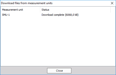
In this case we only had one measurement unit, so only one file needed to be downloaded.
NET menu options
Click the NET menu option to see the list of options:
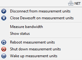
Notice from the menu that you have several useful capabilities:
- Connect/Disconnect from measurement units - connect to all measurement units/releases the connection
- Close Dewesoft on measurement units - closes the Dewesoft application on all measurement units
- Measure transfer speed - measuring the bandwidth (transfer speed) between the measurement units and this client
- Show status - (displays window with the current status of all measurement units)
- Reboot measurement units - reboots the measurement unit computers (useful if they have crashed or hung up)
- Shut down measurement units - shuts down the measurement units (requires ACPI power system on the measurement units)
- Wake up measurement units - starts measurement units (requires ‘Wake-up on LAN’ option enabled on the measurement units)
Setting up a slave client
If you want your unit to be set as a slave client, you must first enable remote connections.
Note that a graphic named Configuration appears which indicates the topology type in which the measurement unit is represented by a picture of a data acquisition system (the picture for reference – it is not meant to look exactly like your particular model).
The white lines represent the TCP/IP network, which must be connected among all MU’s and the client (represented here as a notebook computer, again only as a reference).
The red lines represent the SYNC which must be present if there is more than one measurement unit and you want to show channels from more than one measurement unit on the client at the same time. It also ensures that the data files recorded on each measurement unit are totally synchronized. Unless you have a hard sync, it is not possible to create totally synchronized data files.
In the example above, the system sees one measurement unit on the network, called SMU-1. Select it and click OK at the bottom of the dialog box.
Further setup can be done in Settings.
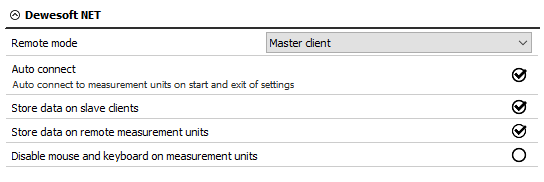
- Store data on slave clients
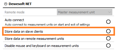
- Store data on measurement units (checked by default, and highly recommended!)
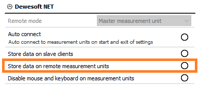
- Lock mouse and keyboard on measurement units
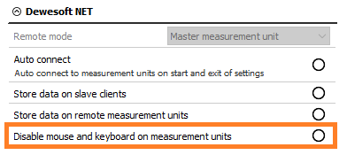
Use the “lock mouse and keyboard” check-box if you want to prevent a local operator from changing any settings on the measurement unit or interfering with the test. With this checked, the measurement unit cannot be operated locally – you will have complete control over the client.
Analysis
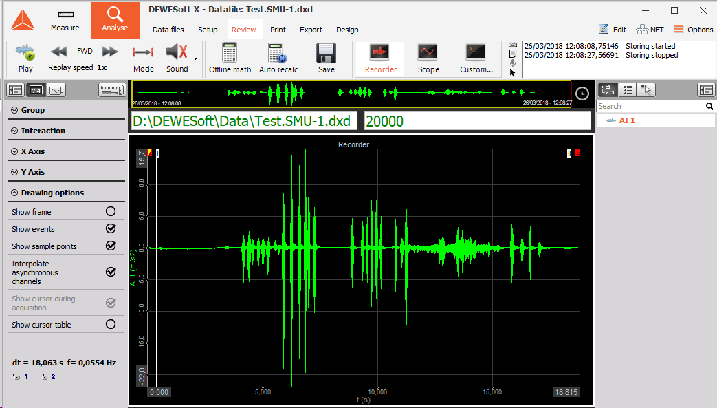
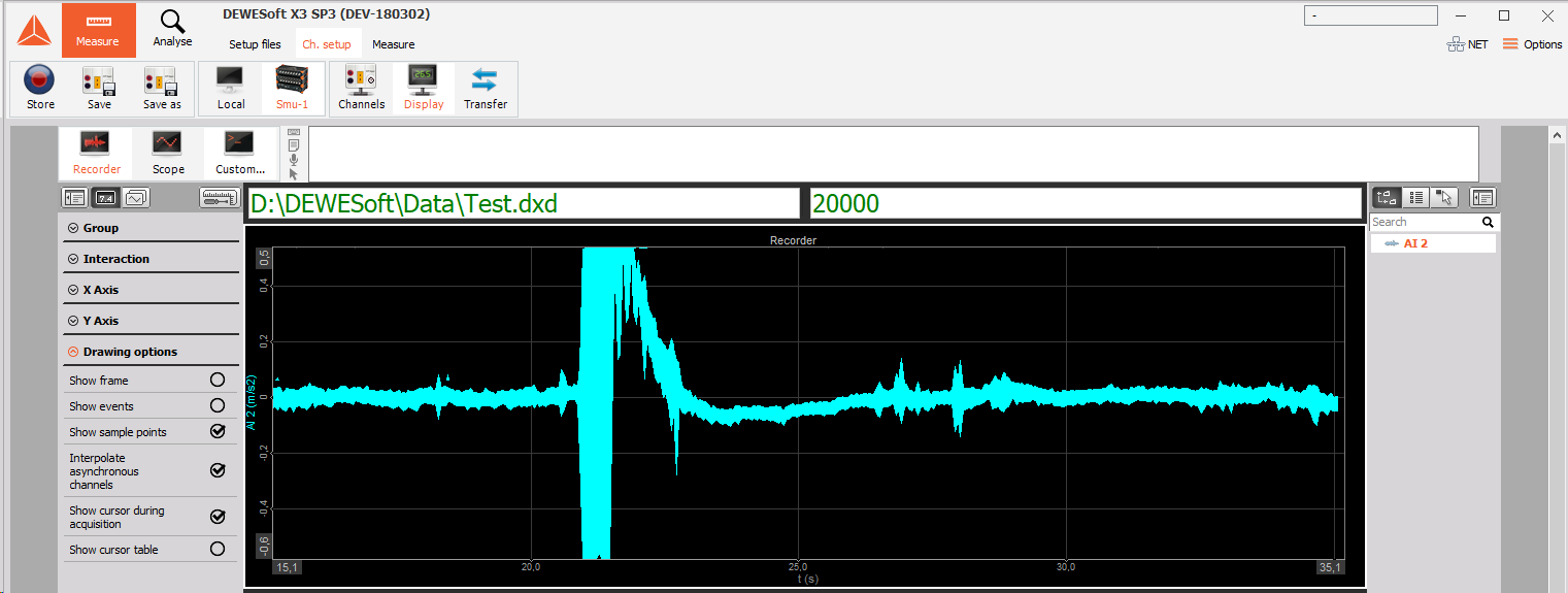
Once the captured data files are downloaded to the client, you can replay them there.
Click the analysis button and locate any transferred files that you have. Notice that we also put the name of the measurement unit into the filename by default, so that you can see that this file came from a measurement unit called SMU-1.
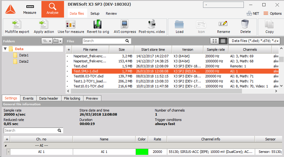
The filename was set to Test. So the name shown here is Test.SMU-1.
Double-click it to open and use the normal tools for analyzing, reviewing, printing and more.
Transfer limitations
USB bandwidth limitation
One reason why we use NET configurations is that USB bandwidth is limited. USB port has a lower bandwidth limitation than an Ethernet port.
USB 2.0 limitation:
- 35 MB/s (in practice \~ 30 MB/s)
- Dewesoft USB limit notice at 26 MB/s
- USB 3.0 does not help upstream
General formula for calculation AI and AO channels:
- Number of channels * Sample rate * 4 bytes/sample (/2 if we use HighSpeed)
- CNT channels: Number of channels * Sample rate * 8 bytes/sample
- CAN channels: Number of CAN ports * baudrate/8
- Slave units (only for clock/trigger sync): Sample rate * 8 bytes/sample
It is very important how the USB port is internally wired in the computer - 30 MB/s per single root hub.
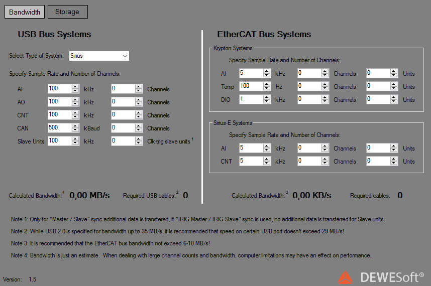
Dewesoft calculator is a simple tool that calculates USB transfer (MB/s) for various Dewesoft devices. You can download it here or by clicking on the picture below.
NET transfer limitations
The limitations of NET transfer are dependent on:
- the speed of Ethernet link in case of large bandwidth
- the write speed of hard drive in case of large data storage
- CPU performance in case of advanced math
We are limited with data transfer because all the PCs are connected together with 1Gb LAN cable.
Next table shows upper limits of transferred data (in samples/second) per 1 PC.
Each PC can store approximately 25.600.000 samples per second and that number of samples can be distributed randomly between measurement units.
With full this sample rate, PC stores approximately 100 MB/s of data:
- 10s for 1 GB
- 1min 40s for 10 GB
- 16min 40 for 100 GB
- 2h 46min 40s for 1 TB
Synchronization
The basic idea of synchronization is to provide a clock signal from a time source. Clock slave receives the signal from the clock provider and the devices are synchronized.
Devices can be synchronized in two different ways:
- Software synchronization - The software synchronization accuracy is around 2-10 ms, which is enough for a simple temperature measurement. This synchronization solution requires no additional hardware.
- Hardware synchronization - This is a hardware solution which can synchronize all USB devices (SIRIUS, DEWE-43, …) and EtherCAT devices (KRYPTON).
Time source
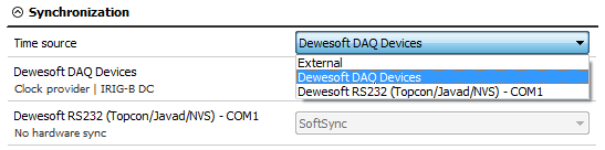 Time source provides a clock for synchronization. It can be selected from:
- Dewesoft DAQ devices (when we have a Dewesoft measurement device connected to our computer),
- External (Clock/Trigger, IRIG-B DC, NTP, GPS PPS),
- PC clock (when we have only a computer, without a measurement device),
- GPS devices (Dewesoft RS232 (Topcon/Javad/NVS), NMEA compatible GPS, …).
Synchronization types are dependent and automatically adjusted from the DAQ devices connected to our system.
Type of synchronization
If Dewesoft DAQ device is selected as a time source, clock provider must be selected from:
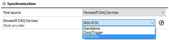
- Automatic - this option automatically selects the best option for synchronization regarding the hardware connected to the system.
- Standalone - only one device, there is no synchronization between devices needed.
- SoftSync - this synchronization solution requires no additional hardware. The accuracy is > 10 ms.
- Clock/Trigger - a clock and a trigger signal are used. With each trigger signal a sample is acquired.
- IRIG-B DC - It contains time-of-year and year information in a BCD format (it contains the information about the absolute time). This is the best way to synchronize the devices because it is the most exact one.
- GPS PPS - Since the satellites are transmitting exact absolute time and better receivers usually output this pulse with a high precision (below one microsecond), we can use this technology to synchronize remote systems - and there is no distance limit.
- NTP - Network Time Protocol (NTP) is a networking protocol for clock synchronization between computer systems. It is less accurate than other methods.

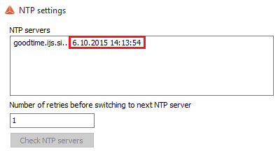
To enter the addresses of the NTP server click the edit button near the drop-down menu. If you want to have more devices synchronized via NTP protocol, the same server address must be entered in all of them.
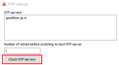
When you check NTP servers, time and date of the server will be displayed. If the server address is wrong, the check will fail.
Synchronization between Dewesoft USB devices
| Accuracy | When to use | Device | |
|---|---|---|---|
| Clock/trigger | ~ 1 us | stationary | Dewesoft, RoaDyn… |
| IRIG-B DC | ~ 1 us | stationary | Dewesoft, Meinberg,… |
| GPS PPS | ~ 1 us | mobile | GPS receiver |
| NTP | + 10 ms | Ethernet | NTP server |
| NTP | + 10 ms | when there is no external time source |
Any Dewesoft device can be precisely synchronized by hardware (Sirius, Dewe-43, Minitaur, DS-CAN2).
When using the NET system, there are several possibilities that can be used for synchronization:
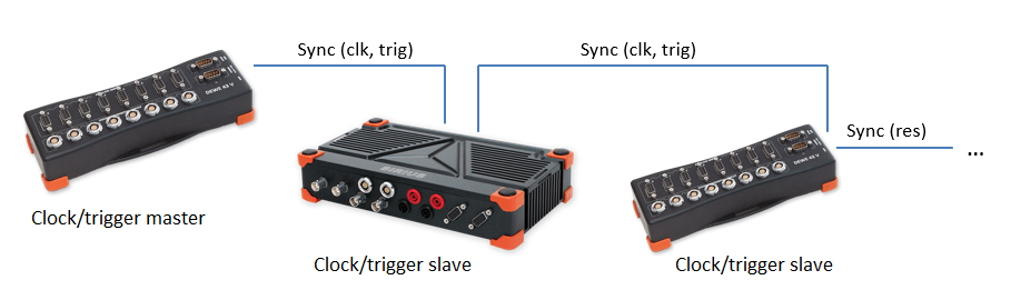
- Clock/trigger - relative time
- IRIG-B DC Master / IRIG-B DC Slave - absolute time
- GPS - absolute time
- NTP - absolute time
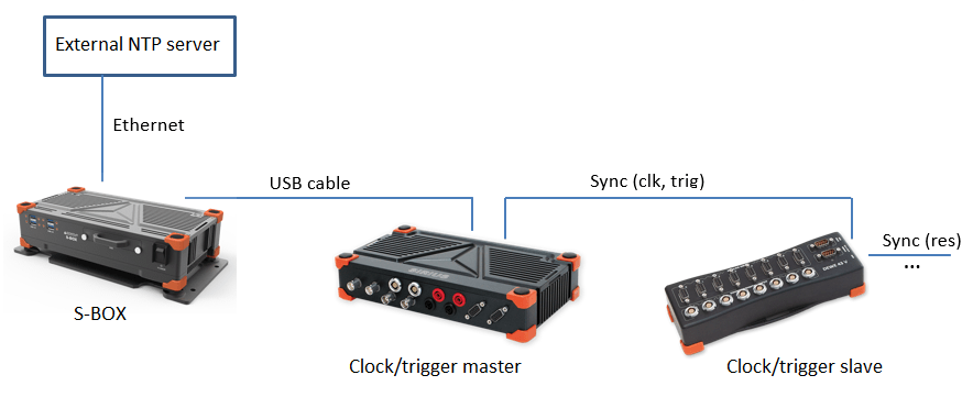
Clock/trigger connection example
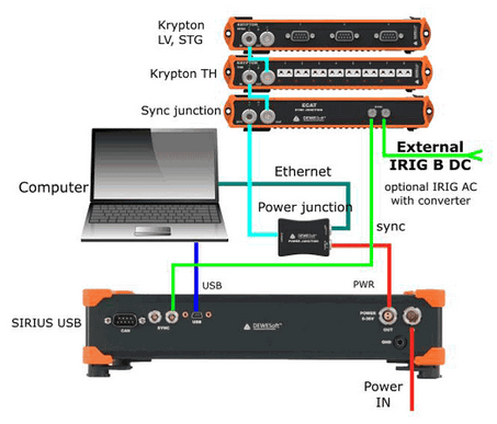
IRIG-B DC connection example of one unit:
- Dewesoft device as IRIG-B DC generator
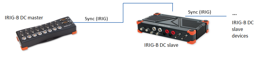
- External IRIG-B DC provider

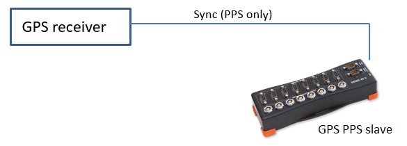
GPS PPS connection example of one unit:
Dewesoft device has a GPS receiver
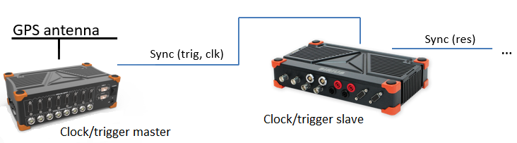
External GPS receiver
NTP connection example of one unit:
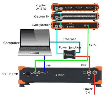
Synchronization with ECAT-SYNC-JUNCTION
ECAT-SYNC-JUNCTION works in the same way as other Dewesoft devices. It is automatically recognized within Dewesoft X software (supported in version X2 SP4). By default, ECAT-SYNC-JUNCTION will be set up to synchronize between KRYPTON EtherCAT® and SIRIUS USB.
With ECAT-SYNC-JUNCTION several connection options are possible:
Synchronization of SIRIUS/DEWE-43 USB with KRYPTON/SIRIUSiwe EtherCAT® devices, where the accuracy of synchronization is microsecond
Synchronization of KRYPTON module with an external IRIG B DC triggering source
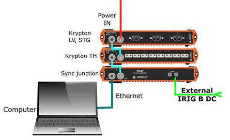
Synchronization of KRYPTON and SIRIUS USB with an external IRIG B DC triggering source
Synchronization of KRYPTON/SIRIUSiwe with triggered cameras
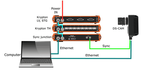
Synchronization of SIRIUS/DEWE-43 USB with KRYPTON/SIRIUSiwe and triggered cameras

NOTE: Dewesoft EtherCAT® devices (KRYPTON) are already synchronized between each other by the daisy chain cable, therefore no additional cables are necessary between them.
Remotely controlling a measuring unit
In this section, we are using only the master client computer to remotely configure and control a measurement unit from this master client. The measurement unit is already connected to it using the steps from the preceding section. All steps are done on the client.
We are not touching the measurement unit at all. It could be a few feet away, on the other side of the building, or miles away. As long as it has a reliable network connection to the client, we can control it from this client!
Local setup
Now click the Ch. setup button. If you know what the Dewesoft Setup screen normally looks like, you will notice a subtle but important difference:
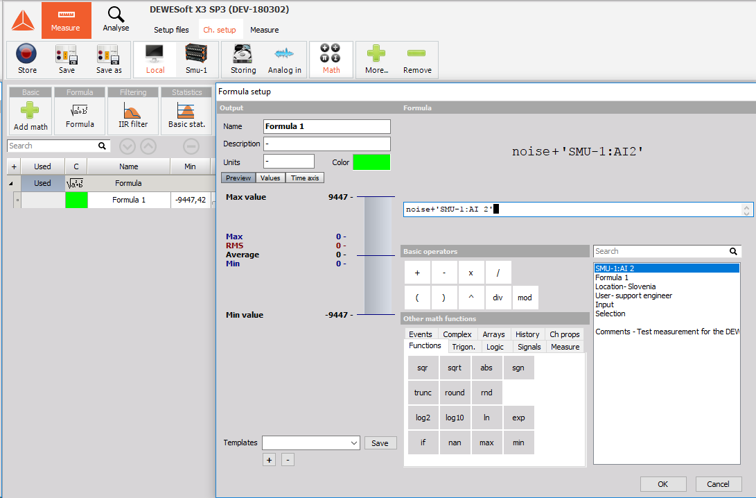
Note the buttons for Local and SMU-1. If you have more than one measurement unit, their names will be shown on this bar as well. The local computer is our master client, so it does not have any real measurement channels of its own. However, it still has Math buttons. It is interesting to note that you can perform math functions in real time on this client using any channels that are transferred from the measurement units! You can even combine channels from more than one measurement unit here in math channels – as long as the measurement units are synchronized!
SMU-1 setup
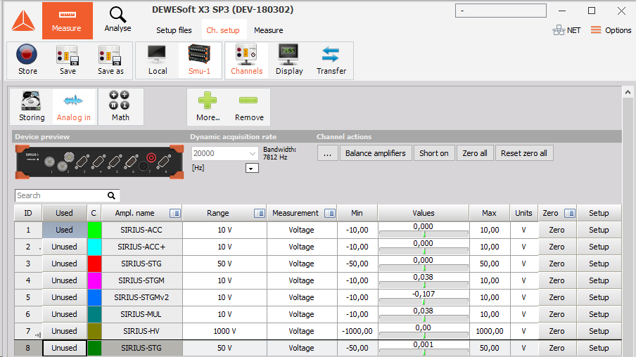
Click on the SMU-1 button so that we can proceed to set this measurement unit up.
You can see that SMU-1 has all eight channels set up to be transferred in real time to the client. Of course, they will also be stored on the local measurement unit, because this has been selected by default on the hardware setup screen, NET page.
Note the three buttons on NET toolbar beside selected WEBSTER:
Channels - setup, activation, and scaling of the actual channels that will be stored
![]()
Display - to have a display screen on the measurement unit for local observers
![]()
Transfer - to set up the transfer from the measurement
![]()
Chanel setup on the measurement unit
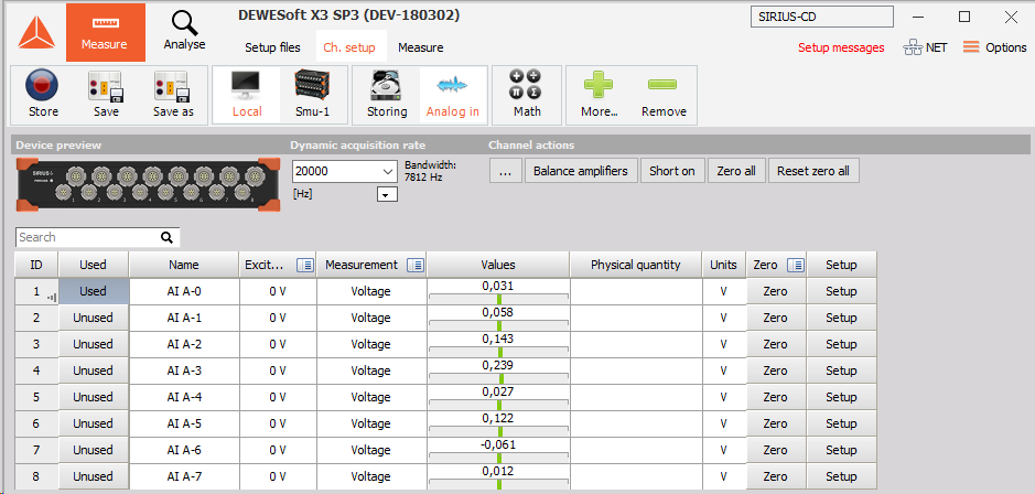
This is perhaps the most critical step of the three because it is the setup, activation, and scaling of the actual channels that will be stored on SMU-1. So let’s start there. Click the Channels button on NET toolbar beside selected SMU-1.
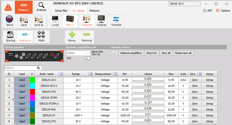
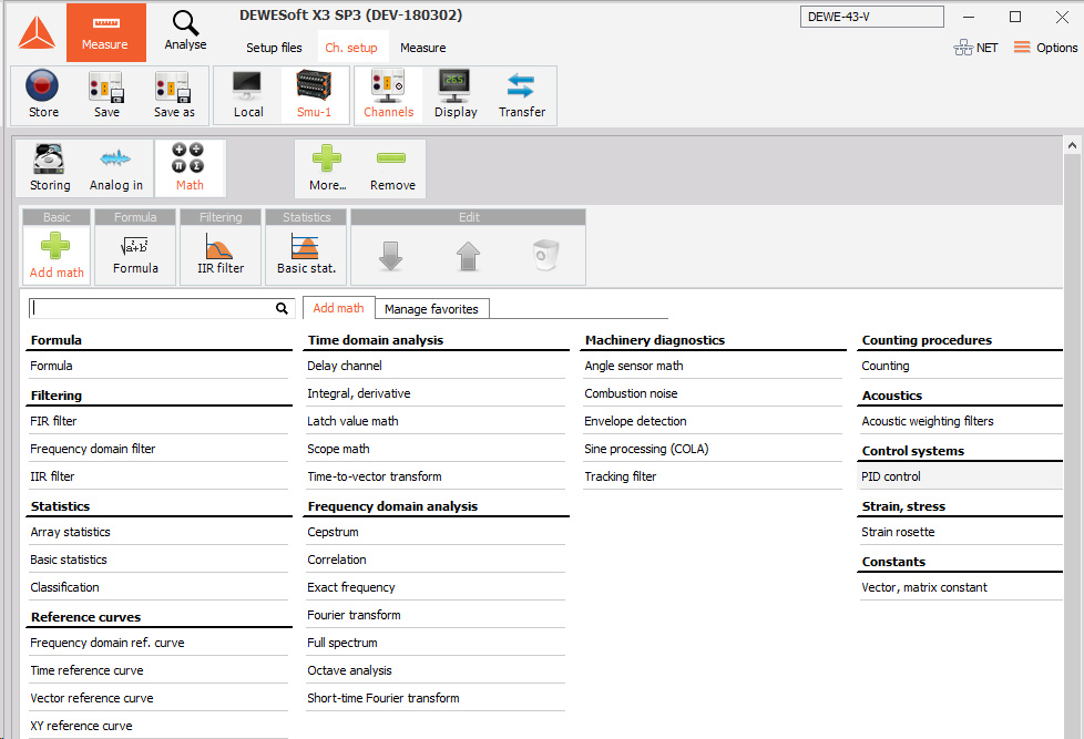
On this screen you are doing exactly what you would be doing if SMU-1 was a stand-alone measurement unit activating channels with the Used / Unused buttons, scaling them using the Set ch. # buttons, and so on. You can also set the dynamic and reduced sample rates, choose a filename, and more. In this example, SMU-1 is a computer with 8 analog input channels. In addition, the Math channels can also be created:
Display setup on the measurement unit
This is only important if you want to have a display screen on the measurement unit for local observers to see. If there is no one looking at the local display on the measurement unit (perhaps it is in a remote location without any people near it), then you can skip this step.
But if you want a local display on the measurement unit, click the Display button on NET toolbar beside selected Testing-PC and then set up the screen as you desire, using the normal Dewesoft methods and conventions for screen design.
It is really important that the client computer has a display which has more resolution than the measurement units! If your measurement units have 1024x768 screens, your client should have the next size up or greater, else you may run into trouble seeing some of the screen objects near the bottom when remotely controlling measurement units from the client.
The display above is the one that will appear on the screen of the remote measurement unit called TESTING-PC! It is not the display that you will see here on the client.
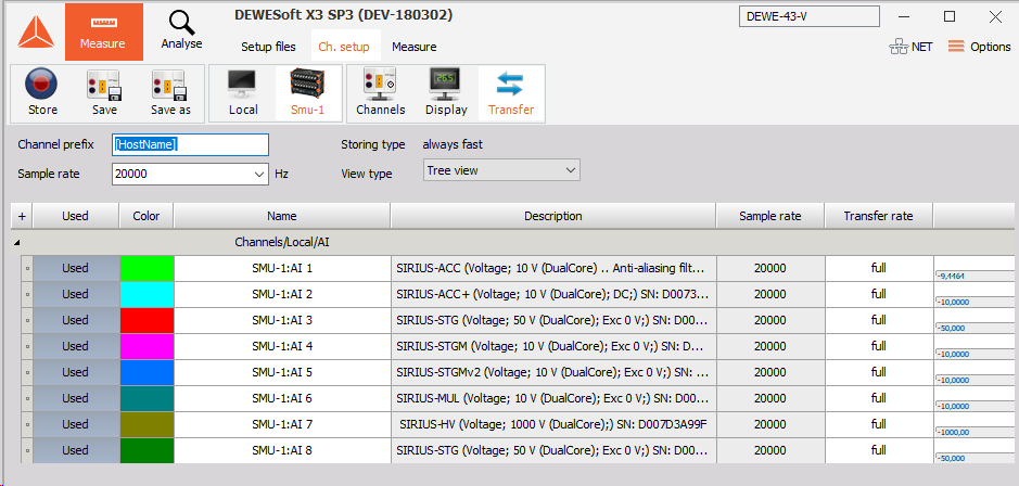
Transfer setup of a measurement unit
Finally, we will set up the transfer from the measurement unit. What does this mean? Transfer: “which channels will be sent across the network during recording, for display on the client”.
That is the entire scope of what transfer means. It has no effect on the actual Storage of data on the client (assuming that local storage is enabled – the default and highly recommended setting).
Therefore, you can have multiple measurement units, each with dozens or even hundreds of channels, and transfer only a few channels – or even no channels – to the client. It will have no effect on the storage of all channels on the measurement units! This is important to understand.
Due to bandwidth limitations of any network, we recommend being prudent about transferring channels – keep the bandwidth in mind and select only those channels that you really need to see on the client in order to monitor and control the test.
In this case, we will transfer all seven channels. Note that all four channels are set as Yes in the Transfer setup screen:
Local Net setup
When the connection was successful, the NET button turns green and the Setup screen appears. Now click the Setup button. If you know what the Dewesoft Setup screen normally looks like, you will notice a small but important difference.
Local setup screen with buttons to the remote setup screens:
Each system setup (local and remote units) can now be accessed via the button bar (yellow indicates the selected unit).
Note the buttons for Local and Testing-PC. If you have more than one measurement unit, their names will be shown on this bar as well. The Local computer is our master client, so it does not have any channels of its own
Math tab
However, the Local computer still has a Math tab. It is interesting to note that you can perform math functions in real time on this client using any channels that are transferred from the measurement units! You can even combine channels from more than one measurement unit here in math channels – as long as the measurement units are synchronized!
Note the buttons for Local and Testrig. If you have more than one measurement unit, their names will be shown on this bar as well. The local computer is our master client, so it does not have any real measurement channels of its own.
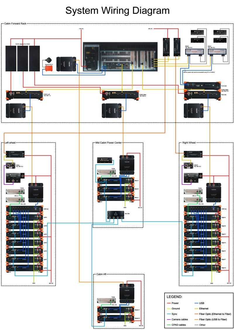
Example of large NET system configuration
An example of a large system connected with the NET system.
Channels:
- Analog, 19 Sirius slices
- XSENS
- GPS
- ARINC
- CPAD
- Power module
- GigE cams
Controlled via Master computer
- Sync: IRIG Master / IRIG Slave
- Three Slave measuring units
- Different SR
Ethernet to optics extenders
- Extensions USB vers optique