ADMA Ethernet
The ADMA Ethernet plugin enables DewesoftX to acquire data from the GeneSys® ADMA 3.0 measurement system. There are four operation modes:
- No Dewesoft hardware: ADMA 3.0 is running stand-alone.
- Master clock: ADMA 3.0 acts as a clock provider for DEWESoft hardware. (expected PPS with raising edge)
- Soft sync: ADMA 3.0 and DEWESoft hardware each run with their own internal clock.
- Demo mode: When no ADMA 3.0 system is connected, DEWESoft will create a virtual one.
Prerequisites
- Dewesoft X3 SP8 or newer software installed,
- ADMA Ethernet extension added to Dewesoft,
- Sync connector in case of using the Master clock mode.
Licensing
The plugin requires a valid DewesoftX ADMA Ethernet license, which is tied to the device itself. To test the plugin, you can use an Evaluation license.
Hardware Connection
The sensors are connected to the measurement PC (e.g. S-BOX) via the LAN port (TCP/IP for data transfer). If more than one ADMA 3.0 system is connected, it is recommended to use an Ethernet Switch. In case of the Master clock mode, the GPS-PPS pin of the signal-out connector on the sensor need to be connected to the corresponding GPS-PPS of the sync connector on a Dewesoft device.
Sync Connector
In case you use the master clock mode, ADMA 3.0’s GPS-PPS pin of the signal-out connector must be connected to the Sync connector of the DEWESoft measurement device (i.e. SIRIUS, DEWE-43): The GPS-PPS pin of the signal-out connector is connected to PPS (Pin 3) on the DEWESoft Sync connector. The ground is connected to GND (Pin 4) of the DEWESoft Sync connector.
Ethernet configuration
ADMA 3.0 is connected to the measurement unit via an ethernet cable for data exchange. To establish a communication between the ADMA 3.0 and the measurement system, the ethernet interface on the PC and the ethernet interface/s on ADMA 3.0/s must be configured to the same IP address range (i.e. the subnet mask must match).
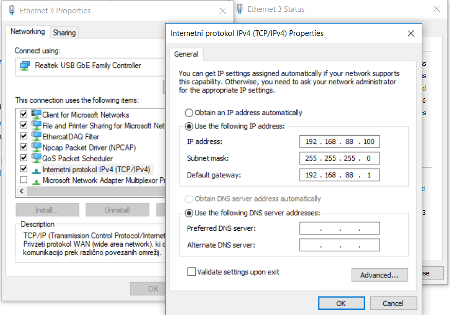
Configuration of the measurement unit’s Ethernet interface: * Define the IP address (here 192.168.88.100) * Define the Subnet mask (here 255.255.255.0) * Define the default gateway (here 192.168.88.1) * Click OK to confirm the settings
All device settings are made through the device’s webinterface. Type http://192.168.88.30 in the address bar of your browser and the ADMA Webinterface should appear (by default, it depends on devices ip address).
*For more information please refer to the ADMA 3.0 User Manual GenSys documentation.
Hardware setup
After you have installed and enabled the plugin, start Dewesoft and go to the Hardware Setup (Option | Settings):
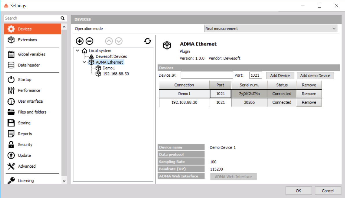
To connect the device with the ADMA Ethernet plugin, you must insert the device’s IP address, port number and press the Add Device button. If you have successfully added the device, the status of the device will be “connected” and the serial number of the device will be displayed. The correct setting of the port is not verified, but if it is set incorrectly, no data will be obtained.
The device data protocol must be set to etiher version 3.3.1 or 3.3.2.
Multiple devices can be connected to one port. Correct port and other device settings can be obtained or set from the ADMA Webinterface.
Master clock mode
In the Master clock mode, the ADMA 3.0 system acts as the clock master, providing GPS-PPS to DEWESoft instruments. An additional cable is needed for this mode.
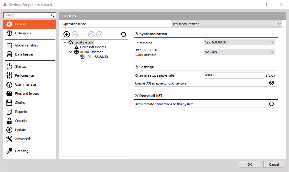
For the Master Mode it is important to set Dewesoft’s synchronization parameter “Time source” to the ADMA 3.0 system.
In case of using two or more GPS providers, for example an ADMA System and a standalone GPS, samples in dewesoft will not be in soft sync mode, but the absolute clock will be used instead.
Soft sync mode
The ADMA 3.0 system can also be used without hardware synchronisation between devices. In this case, synchronized data cannot be guaranteed and will be in the in the range of +-10 ms.
Demo mode
If you would like to test the ADMA Ethernet plugin, you can add a demo device. The Demo device will replay the tipical acquisition. This is useful when trying to get familiar with the steps/events displayed in the graphical interface during device calibration (GPS, Kalman filter).
Channel setup
In addition to the main functionality of activating and setting channels, the control panel is part of the graphical interface.
Successful measurements on ADMA devices require calibration beforehand. The Kalman filter channels show the progress of the calibration, which is highlighted in the control part of the interface.
*For more information please refer to the ADMA 3.0 User Manual GenSys documentation.
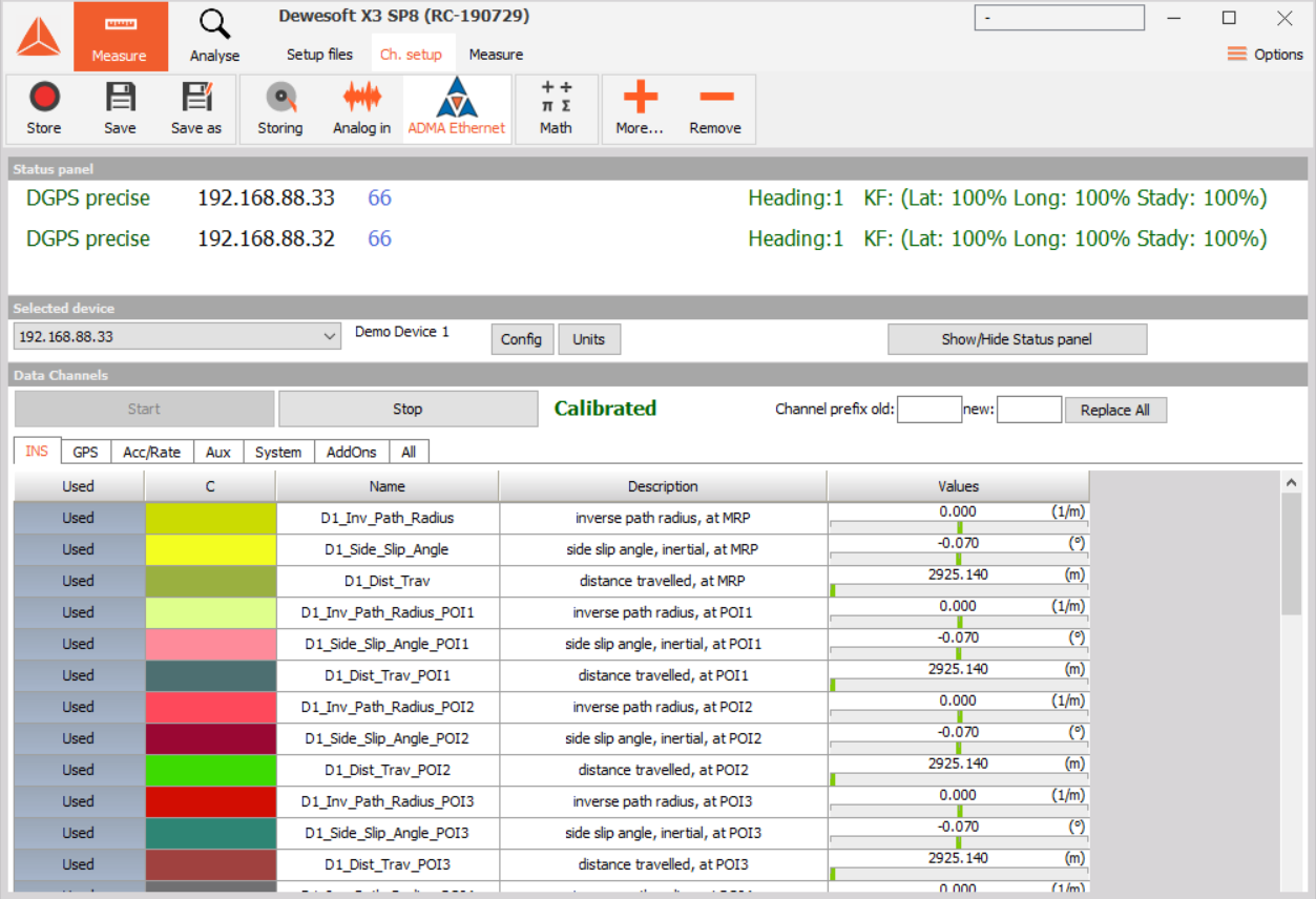
The Main setup window is divided in to three parts. On top is the “Status panel” that outlines the process of the calibration. The panel can be hidden by clicking on the “Show/hide Status panel” button.
In the middle part, you can select one of the registered devices. Based on the selection, the standard channel setup panel is opened on the bottom part of the setup window.
Troubleshooting
- With the correct IP and a connected device, the status will be shown as connected. In case the selected port is different than the one set on the ADMA device then there will be no data acquired and the “setup window | status panel” will display “Stop”.
- If the cable is disconected or if there is no new data for more than 3 seconds, the status text in the “setup window | status panel” will display “Stop”.
- The “no GPS” status text in the “setup window | status panel” indicates that the GPS antena is not connected or that there is no or a poor signal (the antena is indoor).