OBDII
Dewesoft’s OBDII module enables you easy access to diagnostic data of various vehicle subsystems as well as the VIN (vehicle identification number) and the current diagnostic trouble codes. You can define custom diagnostic messages with extensive decoding options.
Prerequisites
- Dewesoft X3 SP7 or newer software installed,
- OBDII extension added to Dewesoft,
- Dewesoft supported CAN device and
- OBDII to CAN connector cable.
Licensing
The plugin requires a valid DEWESoft® OBDII license. To test the plugin, you can use an Evaluation license.
Troubleshooting
If you are having troubles receiving OBD data from your vehicle, you can first check the most common issues listed below.
Check communication protocol
The plugin only supports OBDII on CAN bus, which is mandatory for all 2008+ vehicles sold in the US and is most common in newer vehicles. Currently we don’t support other comunication protocols like: KWP2000 (K-line), ISO9141-2, SAE J1850 VPW or SAE J1850 PWM.
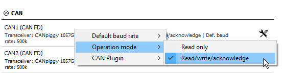
Set CAN operation mode
When choosing CAN port make sure that it has operation mode set to read/write/acknowledge. This allows the OBDII plugin to transmit message requests.
Set correct baud rate
Baud rate should be set according to the CAN communication requirements. The guidelines can be found on this link CAN speed - baud rate
Working with the correct OBDII plugin
Make sure you are using the new OBDII plugin which you can find in settings under extensions. The previous version of OBDII was added directly to CAN port as a CAN plugin. This version is deprecated and should not be used.
Using Dewesoft’s CAN capable device
Whenever using Dewesoft’s devices you should set CAN timeout setting to a value of 1 ms. This setting is not normally available so you will have to navigate to advanced settings and press the combination of keys ctrl + shift + D to activate the debug section.

Connection
You will need a special cable from OBDII male connector to CAN female connector. It is recommended to terminate the connection with a 120 Ohm resistor on the CAN bus side (place it between Pin 2 & 7).
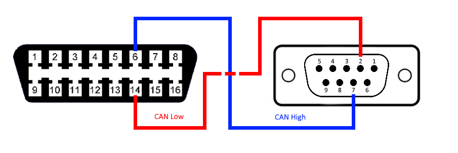
This solution works only with vehicles which have CAN bus implemented as a physical layer on the OBDII interface (generally all the vehicles after 2006). Location of OBDII connector varies depending on the vehicle. Usually, it is located under the steering wheel or the center console. If you have trouble locating it, you should consult the vehicle’s owner manual.
Hardware setup
When you establish the connection, you have to configure OBDII hardware settings, located under extensions. Here you can change:
- Default messages frequency - this frequency will be used as default when adding new OBDII messages.
- Default messages path - set your own default OBDII messages, which you can load in OBDII setup by clicking on load default button, under Import / Export messages category.
- Add/Remove data ports - setup OBDII devices. You can choose between CAN and Test port.

CAN port
Add CAN port when you have connected CAN device to vehicle’s OBDII interface via previously mentioned cable. Here you can change the port’s display name and CAN data port, which will be locked and you will not be able to use it in CAN plugin. NOTE: Make sure that the CAN port’s operation mode is set to read/write/acknowledge and not to read-only mode.
Test port
Test ports are meant for evaluation, quick tests and OBDII setup configuration, without needing to connect actual hardware to your computer. Response data is generated randomly.
OBDII setup
The first thing you will see in the setup screen is tab view where you can switch between previously set devices. Each device has multiple setup options:
- Message / Signal configuration - add and remove defined OBDII messages.
- Scan all messages - enabling this option will put the device into scan all mode. It will periodically scan for supported OBDII messages and send a request for all defined messages with a frequency of 1 Hz.
- Import / Export / Load default messages - import, export and load default set of OBDII messages.
- Scan VIN - scan Vehicle Identification Number.
- Show DTCs - show vehicle’s currently active Diagnostic Trouble Codes.
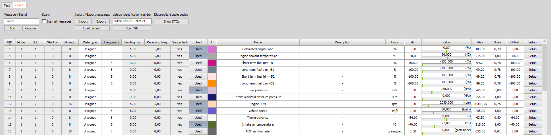
Single OBDII message is composed of one or multiple signals, which represent decoded parts of the received data. All signals are displayed in the grid, with one row representing one signal and some of its parent’s (message) properties. You can edit some message/signal properties directly from the grid (Data type, Frequency, Signal name, etc.), other settings are available by clicking on the Setup button. More on that in the following section. You can toggle signal’s Used property, which will enable or disable Dewesoft’s channel belonging to that signal. While in setup mode, the OBDII device is already scanning the vehicle’s OBDII interface. So you can see the live preview of decoded data for each signal, which helps you determine if decoding is correct.
Message / Signal configuration
Under Message / Signal section you will be able to:
- Search by all cell values,
- Add new message definitions and
- Remove multiple selected signals in the grid.
When you click on Add button under Message / Signal section, or Setup button in the grid, a new dialogue window will be displayed. It is divided into two settings groups:
- Message setup, where you can edit following message properties:
- Pid - unique message identifier.
- Mode - diagnostic mode, also known as service.
- DLC - expected message data size in bytes.
- Frequency - message request frequency.
- Signal list - add or remove signals.

- Signal setup
- Name - signal’s name, for easier identification.
- Description - optional description.
- Units - decoded data units.
- Data type - how bits of data will be interpreted.
- Start bit - start bit of signal’s data within message’s data payload (byte1 = 0..7, byte2 = 8..15 …).
- Bit length - signal’s data length in bits.
- Scale & offset - used for scaling (value = scale * extracted_data + offset).
- Min & max - min & max property of belonging Dewesoft’s channel.
Data decoding
Consider OBDII message with four bytes of data (LSB = A, MSB = D):
| Byte A | Byte B | Byte C | Byte D |
|---|---|---|---|
| 1010 1011 | 1100 1101 | 0001 0010 | 0011 0100 |
From the message’s data payload we extract the signal’s raw values
| Start bit | Bit Length | Raw value |
|---|---|---|
| 0 | 5 | 0 1011 |
| 5 | 16 | 1001 0110 0110 1101 |
| 21 | 11 | 001 1010 0000 |
Data types
You can choose between the following data types:
- String - signal’s bit length must be divisible by 8. Each byte (8 bits) is converted to ASCII character.
- Unsigned - data is converted to an unsigned numeric value.
- Signed - using two’s complement\, data is converted to a signed numeric value.
Import / Export
When you are done setting up OBDII message, you can easily export them to an OBD file, by clicking on Export button. Save file dialogue will be displayed, where you can choose the file name and location. All OBDII messages from the currently selected OBDII device will be saved to that file. That includes all of Dewesoft’s channel properties.
Importing OBDII messages from file to the existing list can be done by clicking on the Import button. You will be met with open file dialogue, where you can choose the file you want to import.
If there are any collisions between existing and imported messages (the same message PID and mode), you can choose to overwrite existing message with the imported one, or you can just skip importing that message. You can also choose options Yes to all or No to all which will do the same for all detected collisions.
Load default messages
Under the Import/Export section, you can find load default button. This action is meant for easy setup of predefined OBDII messages. Plugin installation comes with default messages listed on the following page. In the hardware setup, you can change default messages to your previously exported messages. NOTE: All previous message definitions will be removed and replaced with the default message list.
Show DTCs
By clicking on the Show DTCs button you are able to scan and clear the current vehicle’s Diagnostic Trouble Codes. When the dialogue window opens, you can see to options:
- Scan DTCs - scan current DTCs.
- Clear DTCs - clear current DTCs.

In the upper left and right corner, you can see the status of MIL (Malfunction Indicator Light) and the number of currently active DTCs. Trouble codes are separated by an empty line, you can find additional descriptions on the following page.