Order tracking
For more information about Order tracking take a look at the Order tracking manual
Dewesoft order tracking method is used to extract the harmonic components related to a rotational frequency of the machine. With order extraction, you can see a specific harmonic component which relates to certain machine fault.
Machine vibration pattern - is a mixture of excitation frequencies, usually related to rotational speed, such as unbalance, eccentricity, bearing faults and other machine response functions, which relate to machine natural frequencies based on the structure and mounting of that machine.
Harmonic component - which relates to certain machine fault:
- the first order (harmonic) usually relates to unbalance of the machine
- the second harmonic often relates to eccentricity
- if you have for example 9 rotor blades, 9th harmonic relates to errors on the blades
- if you have for example 31 teeth on the gear, then the 31st harmonic will show the gear mesh frequency…
Final measured vibration - The ratio between excitation and system response is defined by the system transfer curve. So the final measured vibration of the system is a product of excitation force and system transfer curve. Since the transfer curve is fixed, you get different responses for excitations at different rotation speeds. When the excitation passes natural frequency, you get so-called resonance with increased vibration amplitudes which could be fatal to the machine.
NOTE: To measure Order tracking, you need at least one accelerometer for measuring the vibration and one angle sensor for measuring angular data or RPM.
- Required hardware - Sirius, Dewe 43
- Required software - SE or higher + ORDTR option, DSA or EE
- Setup sample rate - At least 10 kHz (in many cases)
For additional help with Order tracking Application visit Dewesoft PRO training ->Dewesoft Web page -> PRO Training.
For help with digital Counters for angle sensors see -> Setup -> Counters.
Add / New Order tracking module
For instructions on how to Add new module see -> Setup -> Add module.
Setup
When an order tracking module is added, you get the following window with the settings for order tracking:
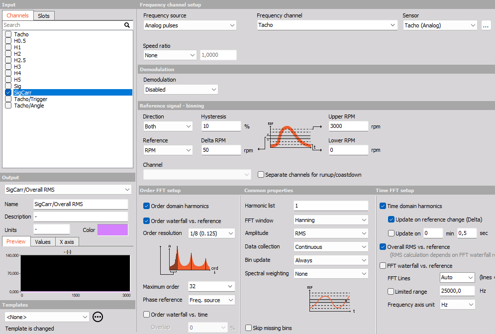
This screen has the following main sections:
- Input channel selection
- Output channel settings
- Frequency channel setup
- Reference signal - binning
- Demodulation
- Order FFT setup
- Common properties
- Time FFT setup
Frequency channel settings
![]()
There are several possible sources for the rotational frequency which can be selected from Frequency source drop-down list:
Counters - should be selected if you e.g. connect an encoder to the Dewesoft instrument Counter input (usually 7 pin Lemo connector). Counters can be an encoder (e.g. 1800 pulses/revolution), a CDM (CDM-360, CDM-720), or a Tacho (digital = TTL levels).
When using counters as Frequency source the Counter channel setup in the background is then controlled (locked) by the Order tracking module, and the counters will not be accessible (grayed out), to prevent double-usage, See -> Counter sensors.
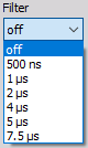
The Counter channel setup can be opened by pressing the ” … ” button, which appears next to the Sensor field: For counters you can adjust the counter input Filter which defines the digital filter of the data to prevent double triggering:
Analog pulses - should be selected when using an analog input channel that measures pulses relating to the rotational frequency. This can e.g. be an analog tacho probe channel measuring 1 puls per revolution, or 60-2 and 36-2 analog signals from a crank sensor (inside nearly every vehicle).
When using Analog pulses as Frequency source, then Angle sensor math is used for getting the angles and the triggers from the analog pulses. Please be careful that the sample rate is high enough to catch the pulses also at high frequencies. The pulse trigger level can be defined by pressing the ” … ” button which appears on the left side of the Frequency channel field.
When the ” … ” button (next to the Sensor field) is selected, you open the Angle sensor math setup window, where the selected analog angle sensor can be defined. see -> Angle sensor math.RPM channel - should be selected when the frequency source is an analog channel which measures the frequency or rotational speed [RPM] directly. If Torsional vibration is used in the setup, it is also be possible to select the torsional vibration frequency as Frequency channel.
When using an RPM channel as Frequency reference, then there is no zero-angle (key phasor) information, and therefore it is not possible to extract the phase angles relative to the angle sensor. Instead phase angles can be calculated relative to the first order, (see Phase reference under Order FFT setup).Signal tracking - can be used in measurement scenarios where it is difficult to mount angle sensors. Instead of using an angle sensor or RPM channel, one of the measured analog input channels can be used to estimate RPM (speed) information. In order to achieve optimal speed estimations the used analog channel should have at least one dominant order to use for tracking and additional parameters should be set. Below the signal tracking settings are shown:
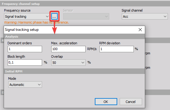
- Dominant orders - is the orders that will be used to estimate the RPM information.
- Max. acceleration - is the maximum change in speed per second that will be included for the speed estimation.
- RPM deviation - indicate how stable the rotational speed is. Depending on this parameter, the search range for the RPM estimate will be broader or narrower.
- Block length - is the time block duration in seconds used for each estimated RPM value The estimator assumes the speed is quasi-stationary within each time block.
- Overlap - is the overlap of time blocks used for RPM estimations. With increased overlap more RPM values are estimated.
Next to the Analysis parameters Signal tracking requires a relation to the physical setup by knowing the Initial RPM. The initial RPM is used to determine how the dominant vibration patterns are related to the Dominant orders. For example, if two orders are dominant, then the Initial RPM helps determine how these orders relate to the 1st order and hereby to the rotational frequency.
The Initial RPM Mode can be set to Manual or Automatic. When Mode is set to Automatic the initial speed is estimated by the software.
Since Signal tracking will estimate speed, it will work similar to using an RPM channel; the phase relation to the zero-angle is missing and instead the phase information should be set relative to the 1st. order phase (described under Order FFT Setup - Phase reference).
Speed ratio
The speed or gear ratio can be adjusted by enabling the checkbox below:
![]()
![]()
With Speed ratio settings it is possible to account for gearing ratios between a fundamental rotation source and the rotation at another component, where the frequency channel sensor might be located.
For example, for practical reasons it might be necessary to perform the frequency channel measurement on a machine component different from the main crankshaft. By using the speed ratio settings the frequency channel can be converted to represent the speed of another component like e.g. the crankshaft.
If the measured frequency channel is measured on an output shaft of a system and the RPM should refer to the input shaft of that system, then the speed ratio should be set to input/output.
Reference signal - binning
![]()
In this section, you need to define the Upper and Lower RPM values (relating to the Frequency source), and whether you want to analyze data while the Direction is runup, coastdown, both or the First detected direction:
![]()
Note that, if the Direction will depend on the Reference Channel and not the Frequency Channel.
Delta - defines the bin width of the Reference Channel (REF) axis in 3D waterfall spectra.
Hysteresis - is used to determine when measured data is assigned to another bin. Hysteresis is described in percentage of the Delta bin width. Assigning data to another bin will only be considered if the Reference Channel value crosses the bin edge by more than the hysteresis percentage.
Reference - determines which channel the REF axis relates to. By default it is set to RPM where the speed (RPM) of the Frequency source will be used.
Alternatively a user-defined Reference Channel can be selected. By using a user-defined Reference Channel the order spectra will relate to that REF channel, for which the Upper and Lower limits must be set. For example if a temperature channel is used as a Reference Channel, then waterfall spectra will be vs. temperature - relating order analysed signals to another physical quantity. In that case the Upper- and Lower REF limits should be set to cover the measured temperature range.
Demodulation
Demodulation can be enabled to analyze e.g. electrical Pulse Width Modulated (PWM) signals and related effects. By demodulating signals the modulating carrier frequency is shifted to DC (0 Hz) and the Order FFT results show the energy content of harmonic components that relate to modulation effects.
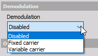
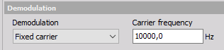
Dewesoft Order analysis supports demonulation based on either a Fixed carrier frequency or a Variable carrier frequency. When selecting Fixed carrier you manually type in the Carrier frequency:
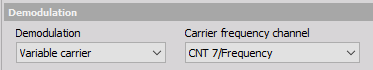
When selecting Variable carrier you have to select a Carrier frequency channel::
Demodulation will only affect order outputs which are selectable under the Order FFT setup section.
When using demodulation, order spectra will span from - Maximum order to + Maximum order, and it is possible to extract negative harmonic components by typing negative values in the Harmonic list found under Common Properties.
Order FFT setup
![]()
In this section, you define the order domain spectral properties, and properties for order extraction.
In the Order FFT setup section the following data results can be selected as output channels:
Order domain harmonics - Complex output values with magnitude and phase information of the defined harmonics over the reference channel axis. In the Harmonics list you define the harmonics that you want to extract.
Order waterfall vs. reference - Order spectra over the defined range for the Reference Channel.
Order waterfall vs. time - Order spectra over a time axis.
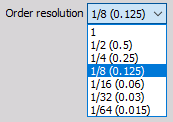
First, you define the spectral Order resolution (line spacing) which also determines the minimum number of revolutions required for producing each order spectrum. If you set 1/16 order for the resolution, you need to acquire at least 16 cycles for each order spectrum and for each data point on extracted order harmonics.
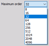
The Maximum order defines highest order contained in output order spectra and thereby also how many orders (harmonics) that can be displayed in the graph widgets. You can select the preferred amount from the drop-down list.
 To set a global maximum order that will be calculated, you must go to Settings/ Extensions/ Order tracking/ Max order to analyse.
![]() The bigger number from these two options (global and local instance) will be selected, so that the right harmonics are calculated.
The bigger number from these two options (global and local instance) will be selected, so that the right harmonics are calculated.
Example: If you set the global ‘Max order to analyze’ to 16, and the ‘Maximum order’ to 32 harmonics for the local instance, then 32 harmonics will be calculated and displayed.
NOTE: This maximum order value together with the maximum RPM defines the sample rate needed for acquisition. If the sample rate is not high enough, this will be written as the error message in the caption
The Phase reference parameter determines how the phase information will be determined for the output order data. By default the Phase reference is set to Freq. source.
![]()
Freq. source - is typically selected when the Frequency source is set to Analog pulses or Counters which provides angular information. The phase of the output data will be calculated relative to the angular sensor keyphasor position.
First order - can be used e.g. when an RPM channel is selected as the Frequency source. First order is used when the Frequency source does not directly relate to the rotation angle. In such cases the phase calculation is missing a phase reference, but it can be determined relative to the First order.
Overlap can be set for ‘Order waterfall vs. time’ outputs. The overlap will determine the percentage of overlapping data between spectra. For example, if order spectra consist of data from 3 revolutions and the Overlap is set to 2/3, then a new spectrum will be produced for every revolution - using 2 revolutions which were also included in the previous spectrum.
![]()
Common properties
![]()
Order extraction setup - You will see orders up to the defined Maximum order in the spectral order results, but if you want to draw Bode or Nyquist run-up plots (in the x-y recorder), you need to have extracted orders available as seperate channels. All sub-orders, integer orders and fractional order components defined by you in the Harmonic list will be available as individual channels with magnitude and phase information.
![]()
Window function - You select (from drop-down list) the FFT window type for calculations of spectral data.
Window functions are used to reduce spectral energy leakage. For order analysis Hanning and Rectangular windows are often used. The rectangular window should only be used when all present order components are placed at defined spectral lines, and not in between lines in spectra.
![]()
Amplitude - determines how the collected data values are scaled. The you can select between rms, peak and peak-to-peak.
![]()
Data collection - determines how analyzed data are collected. You can choose between
![]()
On center of bin - collecting data closest to the center of the bins only
Continuous - collecting data throughout the entire bins
Bin update - is used to define how the output spectrum for each REF bin is calculated.
![]()
You can select the following Bin update types:
Always - When mulitple spectra belongs to the same bin, then only the newest bin values (newest spectrum) will be used in the output for that bin.
First time - When mulitple spectra belongs to the same bin, then only the first bin values (first spectrum) will be used in the output for that bin.
Average - When mulitple spectra belongs to the same bin, then averaging for the individual spectral lines will be performed over all spectra belonging to that bin.
Maximum - When mulitple spectra belongs to the same bin, then the maximum value for all individual spectral lines across all spectra belonging to that bin will be kept.
Depeding on the Bin update type selected, a graph will indicate the bin update mechanism as below:
![]()
NOTE: Bin update is only applied to the output array channels that relate to the Reference Channel Binning, which is:
- Order domain harmonics
- Order waterfall vs. reference
- FFT waterfall vs. reference
- Overall RMS vs. reference
Spectral weighting
Following spectral weighting functions are supported:
![]()
Acoustic weighting - A- and C-weighting are used for sound pressure signals. When analyzing sound and noise signals acoustic weighting filters can be applied in order to take audible human perception into consideration
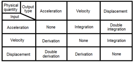
Integration/Differentiation - Integration/Differentiation functions are used mainly for vibration signals to change the physical quantity. A typical scenario for this is when transforming data from the acceleration domain to the displacement domain. The table below illustrates how integration and differentiation functions can be used to transform vibration related physical quantities:
Skip missing bins
Empty bins typically appear when the Delta bin width is too narrow to capture the number of cyclic revolutions required to produce a spectrum. The required number of revolutions for each spectrum is determined by the Order resolution.
- If ‘Skip missing bins’ is enabled, all REF bins that miss revolutions for producing a spectrum will stay empty.
- If ‘Skip missing bins’ is disabled, all REF bins that miss revolutions for producing a spectrum will use an overlapping amount of revolutions from previous REF bins that match the missing part required for producing a spectrum.
Time FFT setup
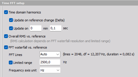
In this section, you define the frequency domain spectral properties, and properties for harmonic extraction in the time domain.
In the Time FFT setup section the following data results can be selected as output channels:
Time domain harmonics - Complex output values with magnitude and phase information of the defined harmonics over a time axis. In the Harmonics list you define the harmonics that you want to extract.
Overall RMS vs. reference - Overall RMS values over the defined range for the Reference Channel.
FFT waterfall vs. reference - Frequency spectra over the defined range for the Reference Channel.
FFT Lines
The frequency line spacing for ‘FFT waterfall vs. reference’ channels can be defined by the number of FFT lines, where the delta frequency (df) is also shown. The FFT lines parameter can be also set to Auto, where the resolution is calculated from the ‘Upper RPM’, the acquisition sample rate, and the ‘Order resolution’. Based on these parameter settings the df that corresponds to frequency width of the order resolution at the Upper RPM is used.
![]()
Limited range
A Limited range can be enabled if the used frequency range should be reduced to a fraction of the original range based on the acquisition sample rate. This can be useful if the input channels are acquired with a much greater sample rate than relevant for the order analysis part. Such channels might have been acquired with higher sample rates due to other types of analysis that are performed in parallel to the order analysis.
NOTE: Both the parameter FFT Lines and Limited range are used for the outputs: Overall RMS vs. reference and FFT waterfall vs. reference.
Frequency axis unit
The unit for the frequency axis on ‘FFT waterfall vs. reference’ channels can be set by the Frequency axis unit parameter. You can select between Hz and cpm (rpm), where cpm is periodic Cycles per minute.
![]()
Update on reference change (Delta) will define when new harmonic values are extracted on the time axis.
![]()
Update on is another way to manage when new harmonic values are extracted on the time axis. It can be used if the reference value is steady, (staying within the same REF bin).
![]()
Output channels settings
The lower-left area displays the output channel settings with fields like in the analog channel setup: Name, Units, Color, Minimum value and Maximum value, also a symbolic display of signal values.
For help with Output Channel list see -> Setup -> Output Channel list.
Order tracking can have more output channels according to the selection of Output extracted harmonics as channels.