Motor analysis
Electric motor analysis is used to improve the motor performance by optimizing the efficiency of the electric input power to the mechanical output power.
The full manual for electric motor power analysis can be found here.
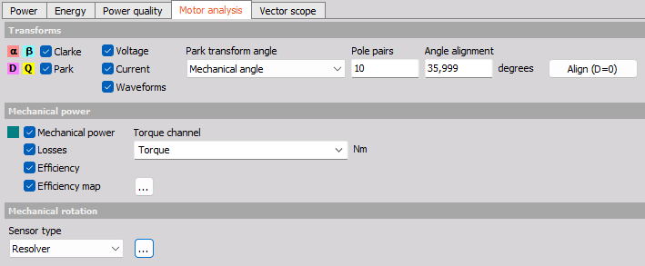
All relevant settings for such types of analysis are found together under the Motor analysis tab of the Power module, as shown below:
Next to the Motor analysis transformations and efficiency calculations, the motor analysis module puts together the usage of multiple processing modules, all able to be set-up through the Motor analysis tab under the Power module. A more detailed description of these used modules and widgets are listed in the links below:
NOTE: The Motor Analysis is disabled when GPU Acceleration is enabled in Power Analysis.
Transforms
One of the tools used for electric motor investigations are Clarke and Park transforms, which can be set-up as shown below:
![]()
Voltage and Current - channels output asynchronous data with a rate equal to the Line frequency divided by the Number of cycles parameter - similar to other power output channels.
Waveforms - channels output synchronous data with the same rate as the input channel’s sample rate.
Clarke transform (abc to αβ0)
The Clarke transform can be used to simplify the analysis of three-phase circuits. It converts three-phase abc components to two-phase ɑβ orthogonal components. The ɑβ-domain relates to the fixed stator frame of reference like the abc-domain does. The difference between the abc reference frame and the ɑβ reference frame is that the ɑβ domain has projected three balanced phase quantities onto two stationary axes, as illustrated below:
![]()
The difference between how a balanced three phase system can be illustrated in the abc domain and in the ɑβ domain over time is shown below:
![]()
It is seen above that for a balanced system, the zero ( or γ) component is equal to zero.
A useful application of the Clarke transform is for the generation of a reference signal used for space vector modulation control of three-phase inverters.
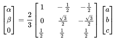
The amplitude invariant transformation formula is given by:
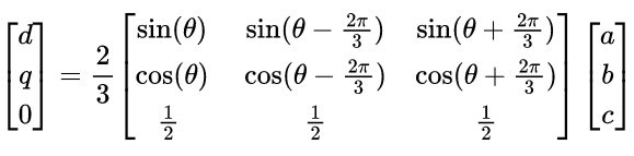
Park transform (abc to dq0)
The dq-domain relates to the rotor rotating frame of reference. The Park transform is conceptually similar to the Clarke transform: Whereas the ɑβ (Clarke) transform is the projection of the phase quantities onto a stationary two-axis reference frame, the dq (Park) transform can be thought of as the projection of the phase quantities onto a rotating two-axis reference frame - a rotational transform of the ɑβ reference frame:
![]()
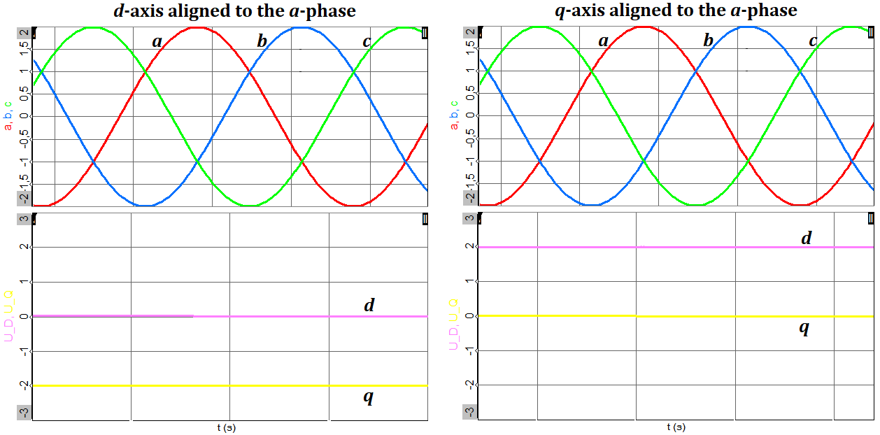
The initial angle alignment is set by the user to either start with the d (direct)-axis at the a-axis or the q (quadrature)-axis at the a-axis. The difference is shown above.
The rotating reference frame can be set to follow either the Electrical angle or the Mechanical angle:
![]()
For the mechanical angle the number of rotor pole pairs are set to determine and sync to the correct rotational angle. In this way the electric and mechanical angle can be aligned.
In practice, the alignment can be done by driving the motor externally while measuring the induced voltage phase together with the mechanical angle. The angle shift between them is then used for the Park transform Angle alignment.
The difference between how a balanced three phase system can be illustrated in the abc domain and in the dq domain over time is shown below:
The amplitude invariant a-phase to d-axis transformation formula is given by:
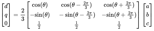
The amplitude invariant a-phase to q-axis transformation formula is given by:
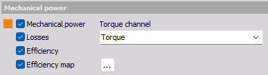
Mechanical power
In order to analyze the power conversion efficiency from electric to mechanical power, a Torque channel has to be specified. The Torque channel drop-down list will contain all channels having the unit [Nm]. With a Specified Torque channel the Mechanical power, Losses and the Efficiency can be determined.
A 3D Efficiency map can also be constructed which is typically set-up to show the motor efficiency across a speed range and at the same time across a torque load range.
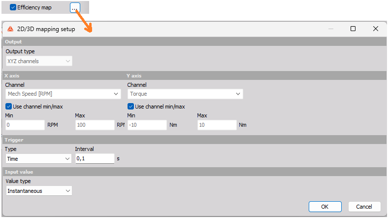
The settings for the Efficiency map is an instance of the 2D/3D mapping module, which is described in more detail under the link.
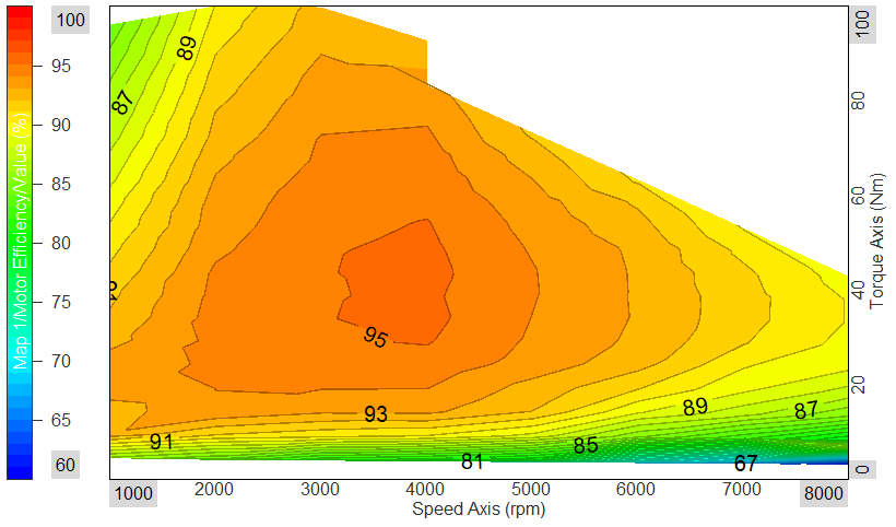
After settings up the speed and torque axis settings to match the measured ranges, the efficiency map can be shown in Measure mode using the Contour plot widget as illustrated in an example below:
Mechanical rotation
When outputs are selected that relate to the mechanical rotation, then the parameter section Mechanical rotation will be visible:
Outputs that relate to the mechanical rotation are the Park transform (dq) channels, and any of the outputs under the Mechanical power parameter section.
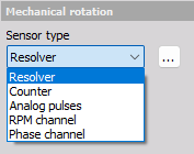
Sensor type
A variety of sensor types are supported for Motor analysis, including Resolver sensors.
If the Resolver sensor type is selected then settings for the used Resolver math instance can be shown by pressing the […] icon as illustrated below:
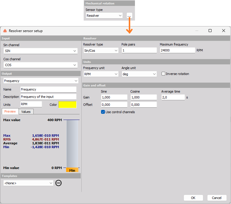
A more detailed description for the different types of sensors can be found here: