Channel setup
Press the Setup button in Analog out Channel list SETUP column to enter the Channel setup screen for each channel.
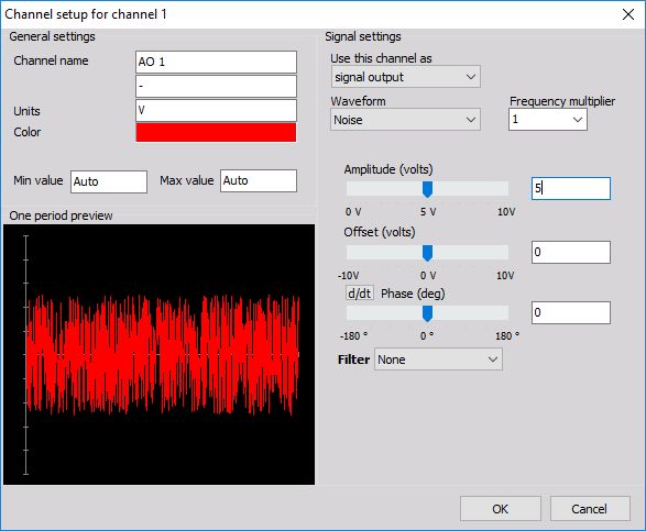
- General settings - you can enter the base channel information on the General settings part of the screen: Channel name, the measurement value, units of measurement, define Color (click on the color bar to change the color for this input) and display range - Min value, Max value, to set a minimum and maximum display value; on the left lower side One period preview of signal is displayed
- Signal settings - on the upper right area of the screen to define signal usage and Waveform type, on the lower right area also sliders to change Amplitude, Offset and Phase and additional signal setting
Signal settings
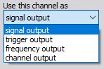
The upper right area contains two elements of Signal setting (signal usage selection in Use this channel output as).
The channels can be used as:
- Signal output for the selected waveform is the default.
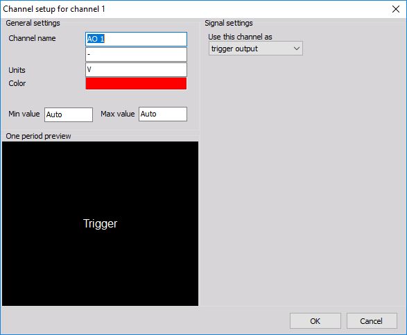
- Trigger output each channel can be set to output a trigger (0 - 5V) instead of signal.
- Frequency output is a voltage representation (-5V to +5V) of minimum and maximum set frequency. This function is mostly used with sweep, step sweep and chirp.
- Channel output output any channel or math function.
Often it is intended to trigger the acquisition on the measurement side when a certain criterion is met. When the sweep is active, the trigger value goes up. It is up at step sweep, at the fixed frequency and during the bursts.
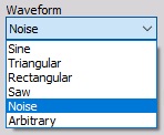
Waveform type
The channels can be used as signal output for the selected Waveform type. Waveform drop-down selection has a direct influence on the settings displayed in the lower right area.
Amplitude, offset and phase angle
All generated channels themselves are available as Dewesoft virtual channels. Also amplitudes, offsets and phase angles are available as channels so they can be put in any visual control to monitor the frequency generator or they can be used in math channel for simulation or control purposes.
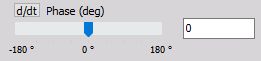
The right area bellow Waveform contains the sliders to change Amplitude, Offset and Phase. For input of precise values, an input field is next to the slider. Simply click numeric field -> and enter the desired value with your keyboard.
The phase setting has an additional option so you can not only define fixed phase but variable phase as well. This can be achieved by pressing d/dt button beside Phase caption (after pressing the button caption changes to Phase change (deg/s).
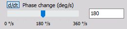
For example, variable phase can create stroboscope effect. One sine wave with fixed phase can drive a shaker, while the other is used for TTL rectangular signal with variable phase for camera triggering to create a stroboscopic video.
The lower left area shows a nice One period preview of the selected signal.
Additional signal setting
For Arbitrary and Noise type of waveform, beside sliders and numeric fields there is also additional signal setting:
- For Arbitrary type of waveform there are sliders and numeric fields in Signal tab, in addition to Points tab for this signal setting -> see -> Arbitrary - Additional settings
- For Noise type of waveform there is also an additional Filter signal setting.
NOTE: For additional help with Noise see -> Noise - additional settings.