Operation modes
In Func. gen. tab of Dewesoft Setup screen several operation mode settings can be chosen and adjustments to them done:
- Function generator mode
- Frequency setting [Hz]
- Time setting [sec]
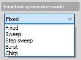
The function generator offers five different operation modes, which are set for all analog output channels:
- Fixed - signals with a constant frequency
- Sweep - sweep frequency from Start frequency to End frequency
- Step sweep - sweep frequency with certain fixed frequencies
- Burst - noise output
- Chirp - sweep frequency with is shorter time and repeated after a defined time
The amplitude will not rise from zero to full amplitude immediately but within a definable time. This ensures that there are no jumps or glitches on the generated signal, which is important to avoid impact shocks to the system under test.
Fixed
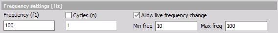
Fixed mode outputs the selected signals with a constant Frequency (f1). The output frequency is the same for all the channels and is defined in the setup.
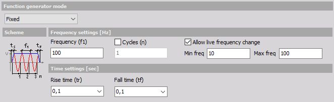
It is also possible to define a number of output cycles if the Cycles (n) check-box is enabled, otherwise, the output is continuous.
The output frequency is the same for all selected channels. If Allow live frequency change is enabled, it is possible to vary the signal frequency during the output within the selected frequency range (Min frequency and Max frequency).
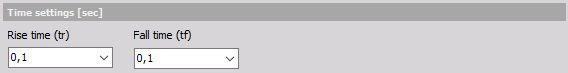
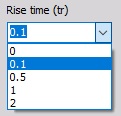
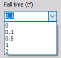
To avoid jumps in the signal on Rise time (tr) and Fall time (tf) at the beginning and the end, the signal output can be set with the selection from drop-down list.
APPLICATION: Fixed mode is used if a defined waveform should be output without changing the frequency or amplitude automatically. Such a function generator is valuable in laboratory testing of electronic circuits, power amplifiers, filters and so on. Also, it provides a great base for calibration procedures. Multiple channels ensure a great chance to test delays and phase errors.
Sweep
A sweep is defined by a Start freq.(f1), an End freq. (Hz) - f2 and a Sweep time (t1).
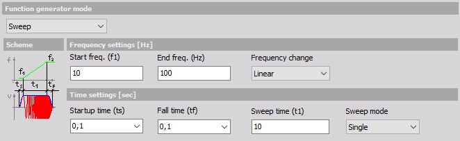
Startup time (ts) and Fall time (tf) define the ramp slope at the beginning and the end of the sweep.
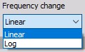
Additionally, the Frequency change of the sweep can be either linear or logarithmic to provide more cycles at lower frequencies and can be selected from the drop-down list.
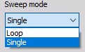
Two Sweep modes are selectable from the drop-down list, Single and Loop. In Single mode, you will get a single sweep output only, at loop mode the sweep is output continuously.
APPLICATION: Sweeps are useful for testing electronic circuits like filters as well as in automated modal analysis.
Step sweep
The step sweep mode is a special procedure for modal testing, where the signal remains at certain fixed frequencies to allow the structure to settle to that frequency. In addition to this more exact frequency resolution of the transfer function can be achieved with smaller steps. Even though this procedure is the slowest to finish the test, it provides the most accurate results.
In the middle, the frequency steps can be one channel defined as the trigger channel and this one can trigger the acquisition system to acquire the results of the modal test.
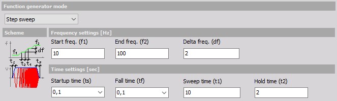
Start freq. (f1) and End freq. (f2) have a similar function to sweep mode, Delta frequency (df) defines the width of frequency change during Sweep time.
Sweep time (t1) defines the sweep duration to the next frequency step, Hold time (t2) sets the duration where the frequency keeps fixed.
Startup time (ts) and Fall time (tf) define the ramp slope at the beginning and the end of the function.
APPLICATION: This mode is mainly used for modal structural tests.
Burst
In burst mode Startup time (ts), Fall time (tf) and Hold time (t1) can be defined. Within the burst, we can choose to have any signal, but in practice, noise is usually used as the base generated signal.
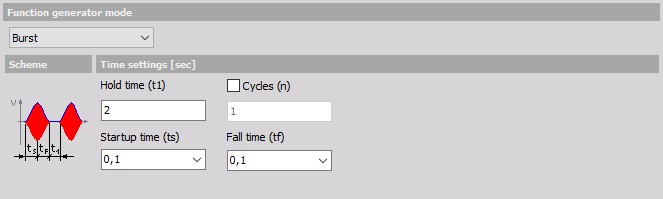
Within the startup and fall time, you get noise output.
If the Cycles (n) check-box is enabled, it is possible to set the number of burst to output.
APPLICATION: Bursts are usually enhancements of the noise excitation for measuring transfer functions. With the burst mode, the need of using windows for frequency analysis (and therefore errors caused by windowing) is eliminated. They are useful at testing response characteristics of the systems.
Chirp
The chirp mode generates a signal which changes its frequency within a certain time. It is similar to the sweep mode, but in chirp mode, the sweep time is shorter and the function is repeated after a defined time.
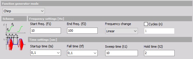
Start freq. (f1) and End freq. (f2) define the frequency range of the chirp. The Frequency change can be either linear or logarithmic. Additionally, it is possible to define the number of chirp Cycles (n) to output. The time settings also contain Startup time (ts) and Fall time (tf) which defines the ramp at the beginning and the end of the chirp, Sweep time (t1) - the chirp duration - and the Hold time (t2) between two chirps.
Chirp mode is similar to burst, except the short sine sweep instead of the noise. Chirp better defines the frequency range than the burst.
APPLICATION: The chirp signal is used for spectral analysis of nonlinear systems.