Encoder
Encoder is a wheel (or linear bar) with marks on it. We usually have encoders with two marks (e.g. A and B signal) with a phase difference of 90 deg. one to another to determine the direction of movement and a zero pulse - one pulse per revolution which can tell us the absolute position of the encoder (e.g. 0° pulse).
- Required hardware- Dewesoft USB
- Setup sample rate - At least 1 kHz
For additional help with Encoder setup visit Dewesoft PRO training.
X1, X2, X4 modes
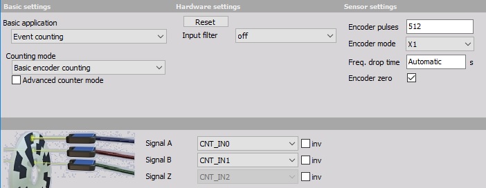
- We choose ‘Basic encoder counting’ as the Counter mode.
- Then we choose the Signal inputs: Signal A and Signal B (e.g. CNT_IN0 and CNT_IN1). Signal Z (e.g. CNT_IN2) is preset by Dewesoft. Signals can be selected from the drop down lists.
- We set the Encoder mode to:
- X1 - to measure just the rising edges of input A - the output of this counter is the counter which counts up when signal A leads signal B and counts down when signal B leads signal A; the positive edges of the signal A is used to make the counts
- X2 - measures rising and falling edges of input A; therefore the resolution will be increased by a factor of 2 (also the scaling has to be changed)
- X4 - mode measures rising and falling edges of both signals signal A as well as signal B, the resolution of the measurements is therefore increased by a factor of 4 (also the scaling has to be changed)
NOTE: The X2 and X4 modes are extremely helpful if we have slow movement (for example with linear encoders) because it will actually increase the resolution of measurement by a factor of two or four. If we have fast dynamic measurement (like torsional vibration) it will sometimes introduce more errors if we use X2 and X4 mode, because those two modes assume that the gap ratio is exactly 0.5 and that the encoder electronics switches exactly with the same speed between dark and light areas. We can evaluate this error with Period and pulsewidth measurement —> Timing modes.
4. We set also the Input filter to match our highest frequency to prevent double counts.
For more information about Counters see —> Counters hardware parameters.
Zero pulse
The zero pulse is used to reset a measurement when a Z pulse is recognized.
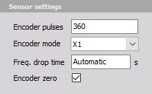
The only change to the setup is to check the Encoder zero check box. This will reset the counter value to 0 when a zero pulse is passed. We also need to set the number of Encoder pulses for internal calculations.
IMPORTANT:
The counter value is reset only when:
- A signal is High AND
- B signal is High AND
- Z signal is High