ETHERNET RECEIVER
The Dewesoft Ethernet Receiver module can listen and acquire the information transmitted on an Ethernet communication protocol. Being able to receive with any type of ethernet communication allows you to send DewesoftX information that can be centralized with other collected information within the DewesoftX software. This is commonly referred to as an ethernet “sniffer”, allowing the user to view, apply engineering units, and record information broadcasted over ethernet.
The Ethernet Receiver is written only to receive data. Transmission is not possible via this plugin.
NOTE: Required Software - Dewesoft Ethernet License (obtainable from your Dewesoft point of contact)
Enabling Ethernet Receiver
Ethernet Receiver is a plugin which needs to be added into your measurement setup once you already installed it.
With plugin version 4.3.3 and older (included in DewesoftX version up until 2023.1) the plugin can be added via the following steps:
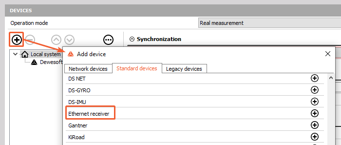
1) Open Options (top right corner) or click on Devices button on top of the window
2) Click Settings or click on Devices button on top of the window
3) New dialog box will appear.
4) Clicking on the “Extensions” on the left side will allow you to press the “+” button creating a new dialog box with a list of Extensions.
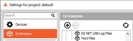 In which the ethernet receiver will be an option.
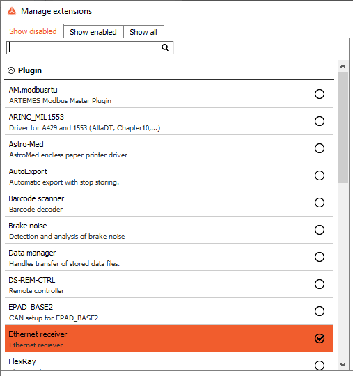 5) Check the box on the right side and then hit OK, then OK.
With plugin version 4.4.0 or higher (included in DewesoftX version from 2023.2) the plugin can be added via following steps:
The step first three steps are the same as before 4.) Press plus button (to add device plugin) 5.) Under the Plugin you will found an option Ethernet Receiver
Adding New Ethernet Streams
When in channel setup, click on the Ethernet receiver module to enter to its settings. To add an ethernet stream please click on the plus button on the upper right corner of the module setup screen.
When the “+” sign is selected the additional pop-up window will appear.
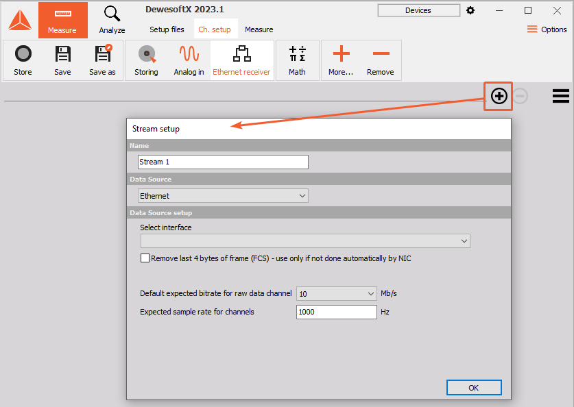
At this point, the user will be required to define the critical parameters of the data source and name the ethernet stream.
Name - The user can name this stream accordingly
Data Source - Three options are available at this dropdown- UDP, Ethernet, or Dewesoft Channel
UPDATE 4.2.3 Multiple Ethernet Input Streams: Multiple streams inputs are allowed and can be seen by the tabs on the top section of the ethernet reciever. To add additional streams, follow the above instructions and setup accordingly. Names changed within the “Name” section will be reflected within the tabs name for quick reference.
The Three Data Sources
UDP
UDP, also known as RFC 768, is a communication protocol. UDP uses a basic connectionless communication model with minimal protocol mechanisms. UDP provides checksums for data integrity, and port numbers for addressing different functions at the source and destination of the datagram. It has no handshaking dialogues, and thus exposes the user’s program to any unreliability of the underlying network; there is no guarantee of delivery, ordering, or duplicate protection.
An example usage would be internet protocols such as DNS, SNMP, RIP, and DHCP. Practical applications include real-time audio and video applications as a loss in data only creates a slight degradation in quality rather than a large delay if lost packets are retransmitted.
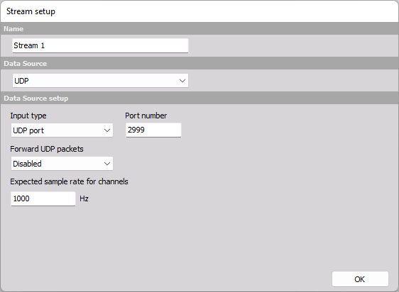
Input type: There are two options for Input type: UDP port or Replay file.
Forward UDP packets: The UDP packets can be forwarded to UDP port or Replay file. By default the forwarding of UDP packets is disabled.
Ethernet
Ethernet is the traditional technology for connecting devices in a wired local area network (LAN) or wide area network (WAN), enabling them to communicate with each other via a protocol — a set of rules or common network language. Ethernet describes how network devices can format and transmit data so other devices on the same local network segment can recognize, receive, and process the information. Ethernet is typically less vulnerable to disruptions.
Ethernet is used in settings where high speeds, single cable operations are required. Communications between nodes can be accomplished with ethernet with ease as the cost is low, all are reverse compatible, and have an established history of great data transfer quality
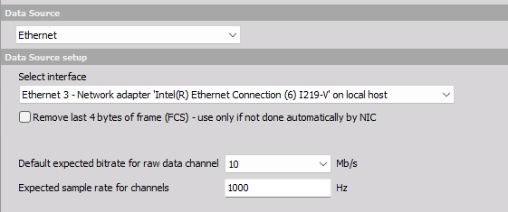
- Using the dropdowns within the “Select interface”
- This will tell the software the source of the information, this can take the form of WiFi, Ethernet, or any Local Area Networks (LANs) that may be connected.
If you have a fast stream with shorter frames, you should reduce this value to boost the performance and reduce the data file size.
Default expected bitrate for raw data channel- This is selectable between 1, 10, 50, and 100 Mb/s. Default is 10 Mb/s.
Expected sample rate for channels - User selectable to set the sample rate for all ethernet parameters collected.
NOTE: Dewesoft Ethernet module cannot read Bluetooth traffic because of the communication protocol differences.
Dewesoft channel
This allows the user to use a Dewesoft hardware channel as an input into the software.
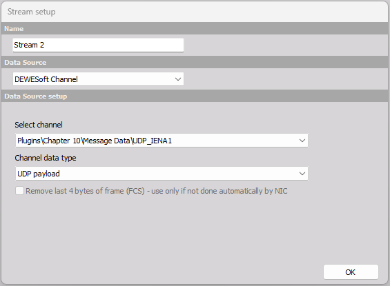
- Channel data type: UDP payload
This option enables streaming UDP data that contains only the payload.
UDP frame payload:
With Ethernet Receiver it is possible to then create Ethernet frame by adding the required packet headers by selecting Ethernet frame as Filtered frame type:
Settings
Once the input is selected and properly set, a setup screen will populate with the following options
Import/ Export
Import and Export feature will allow you to transfer ethernet definitions and locations of data. If a user defines the ethernet locations of data, they can export that information to another system without having to re-input locations. The opposite is true with the importation section. A user-defined ethernet definitions can be take into Dewesoft allowing faster mapping of data for use and collection.
This can be for individual chains or all chains within the file. Import will accept previously establsihed and defined files. Two options exist here for overwriting same name filters if found or import as new keeping existing names and imported chains will be treated as new imports.
Filter Chain
A filter chain is a set of selections that are required by the user to ensure that data streaming through the DewesoftX system is collected properly. This set of selections also allows the filtering of exact parameters through the stream. A filter chain is considered the “mainline” data source. Each stream is allowed multiple filter chains allowing you to add as many ethernet streams required inside of which you can select each data channel for use.
MASTER CLOCK mode: When data from the Ethernet stream is used as source of synchronization (masterclock) for DewesoftX, all defined filter chains must have the absolute Timestamping option selected. This is currently the IENA timestamp option.
A new chain is added by selecting “+” under “Filter chains”. Filter settings box will appear.
You will be able to see data packets coming in (frame preview on bottom).
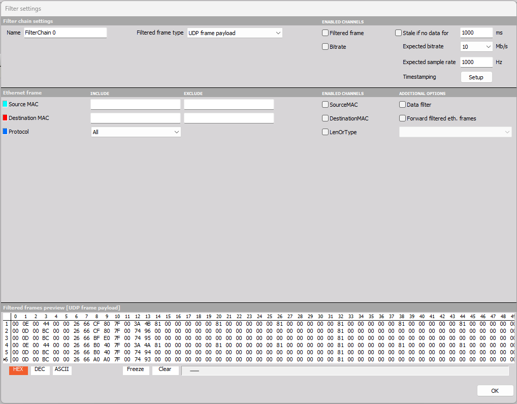
The Filter Chain is used to filter out ethernet frames (i.e. by MAC address, IP address, packet type)
 * Name- This allows you to change the name as required
* Filtered Frame type- a dropdown box allows the choice of Ethernet Frame, Ethernet frame payload, or UDP frame payload
* Enabled Channels- you can check the radio boxes to enable Filtered Frame or the Bitrate. You can enable a Stale warning at a preset trigger if the radio box is checked for a user-defined limit in ms.
* Expected bitrate will allow you to select between 1, 10, 50, and 100 Mb/s.
* Name- This allows you to change the name as required
* Filtered Frame type- a dropdown box allows the choice of Ethernet Frame, Ethernet frame payload, or UDP frame payload
* Enabled Channels- you can check the radio boxes to enable Filtered Frame or the Bitrate. You can enable a Stale warning at a preset trigger if the radio box is checked for a user-defined limit in ms.
* Expected bitrate will allow you to select between 1, 10, 50, and 100 Mb/s.
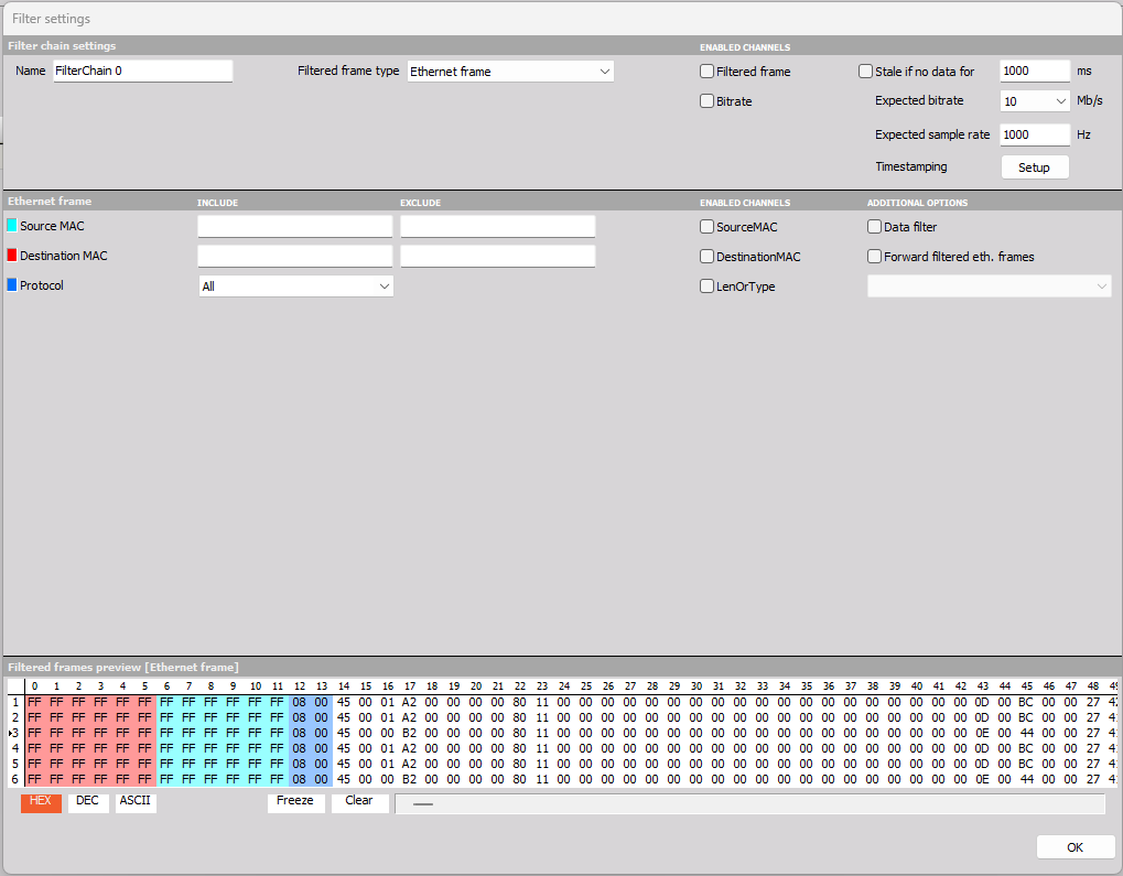
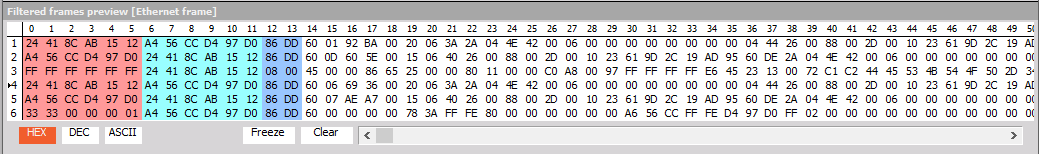
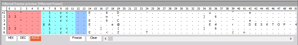
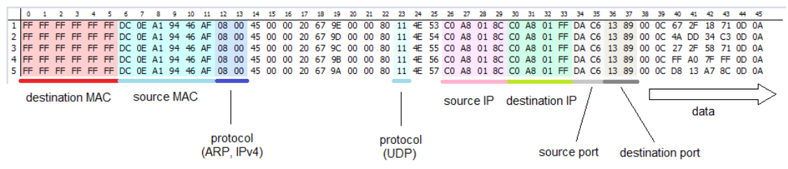
In the Ethernet frame section, you can see a preview of the stream on the lower half in real-time. Each section is color-coded. For example, Source MAC (teal in color) can be seen in the preview window in columns 6 through 11.
Under the enabled channels header, you can select which channels you would like to use. SourceMAC, DestinationMAC and/ or LenOr Type.
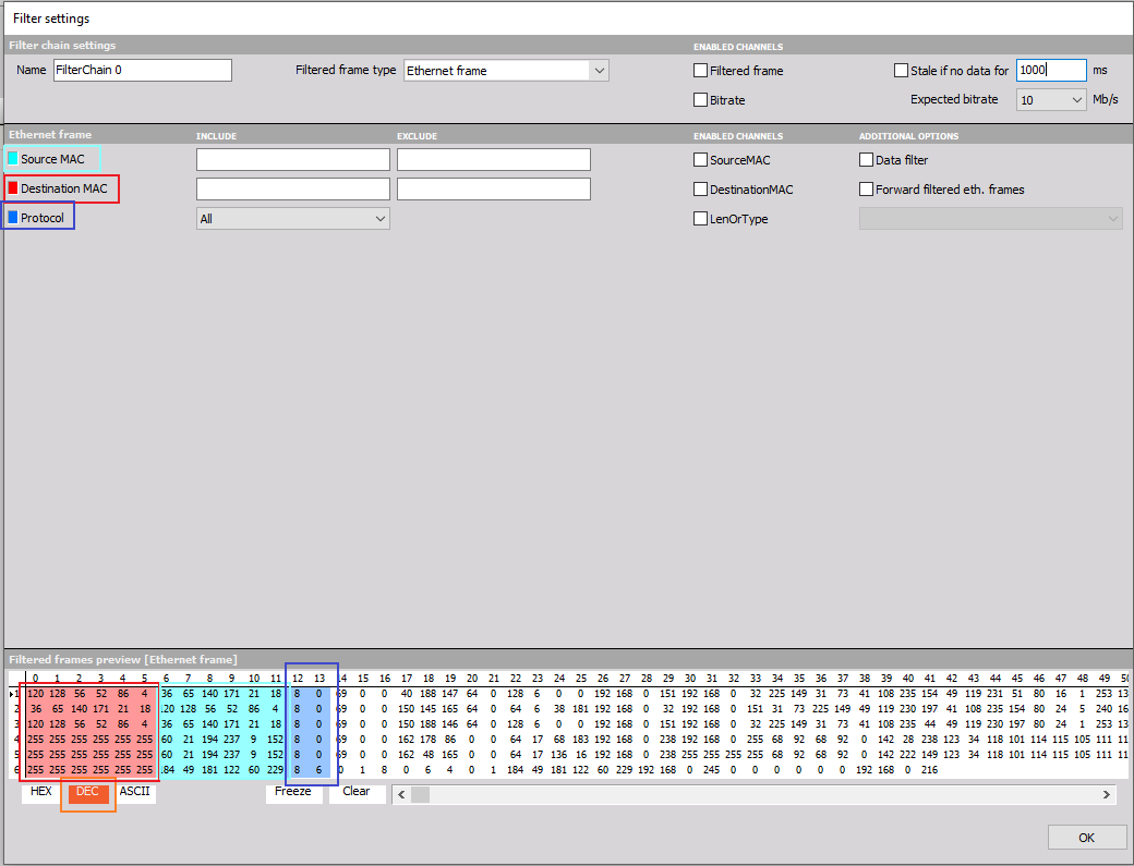
If you know the exact position of the string, you can search for specific bytes/characters with the Data filter.
* If Data filter is selected, an additional dialog box will appear below, allowing filtering options such as selecting the start byte within the ethernet frame. You can also filter by Byte array, ASCII, and Frame identifier. Specific Byte arrays can be manually added in the format specified within the dialog box.
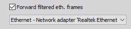
Forward filtered eth. frames can be selected. A list of available interfaces will appear when the radio box is selected. This will allow processed data to be retransmitted via the selection made within the dropdown menu.
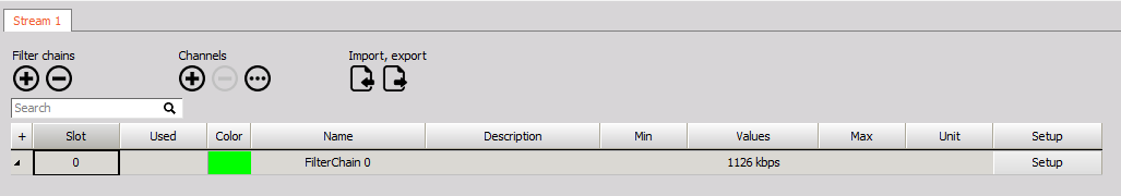
In the lower-left corner, there is a switch that allows the preview of HEX, DEC, and ASCII in plain text. You can also clear or freeze the actual view if you are not sure if the data is moving.
HEX
 DEC
DEC
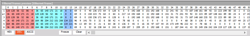 ASCII
ASCII
Enabled channels- Under the header there are 2 enabled channel options.
Filtered Frame- checking this box will allow all data collected within this stream to be exported. This will not allow individual parameters to be displayed but instead collect ALL data. The NIC card will attach a time stamp as the packets cross the card and then organize them accordingly.
Bitrate- This will allow the bitrate to be displayed.
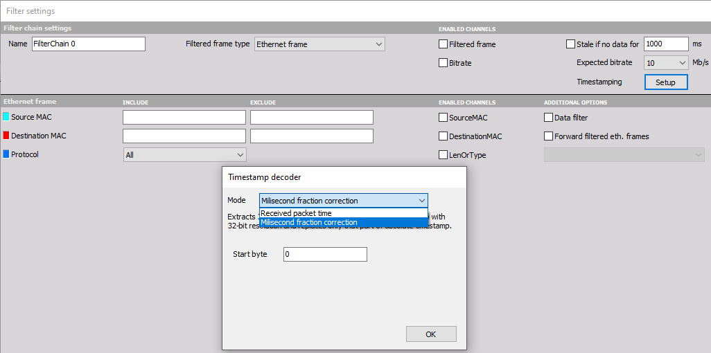
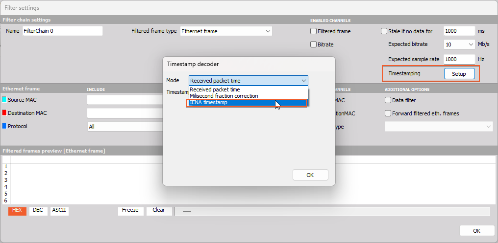
Timestamping
Each Filter Chain can have different timestamping source - currenlty there are three different options: * Received packed time * Millisecond fraction correction (relative time source) * IENA timestamp (absolute time source)
This Millisecond fraction correction mode is used to correct the millisecond in timestamp of the packet. When the ethernet card receives the packet it assigns a timestamp to the packet. This assigned time can be seen with the Received packet time mode. The Millisecond fraction correction mode has the ability to correct milliseconds of the packet timestamp. The timestamp decoder in the Millisecond fraction correction mode reads the 32-bit Unsigned Integer from the packet and calculates the milliseconds. The user needs to write the correct milliseconds into the packet and define the start byte in the packet where the corrected milliseconds are written.
The milliseconds are represented as follows: 2^32 = 1000 ms (1/2)*2^32 = 0.500 ms
The Ethernet Receiver module also supports IENA timestamp. The IENA is the application layer protocol developed by Airbus that defines the packet header and packetization rules for the transmission of acquired data as UDP/IP packets. The IENA partitions logical groupings of data into packet streams, each uniquely identified by an IENA Key.
Example preview of UDP packets
Depending on the used protocol, the packets will change (e.g. with IPv4 the IP addresses would be longer).
Channel
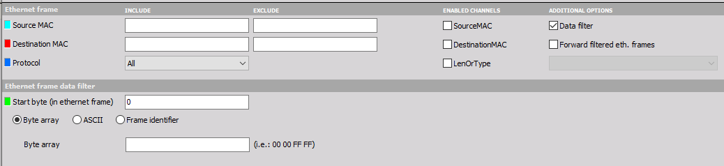
The last step is to add a channel. 0_0 channel is always put below the selected Filter Chain.
Press the “+” sign under the Channels on the top section.
Then select “Setup” which enters the channel setup screen
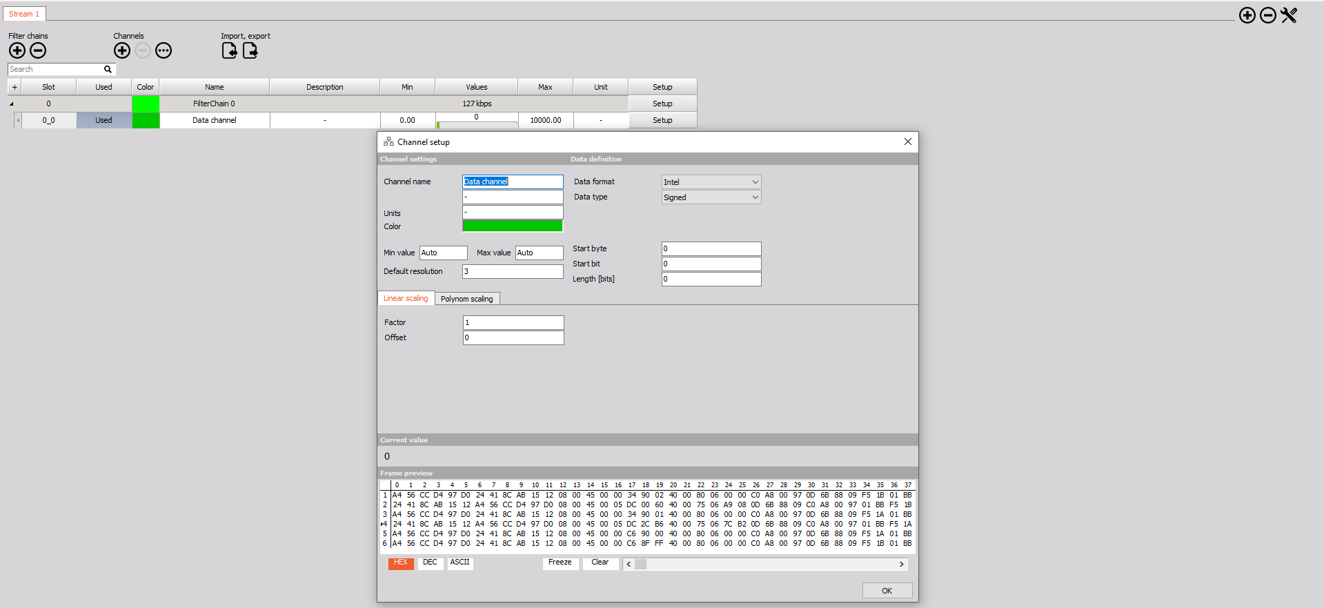
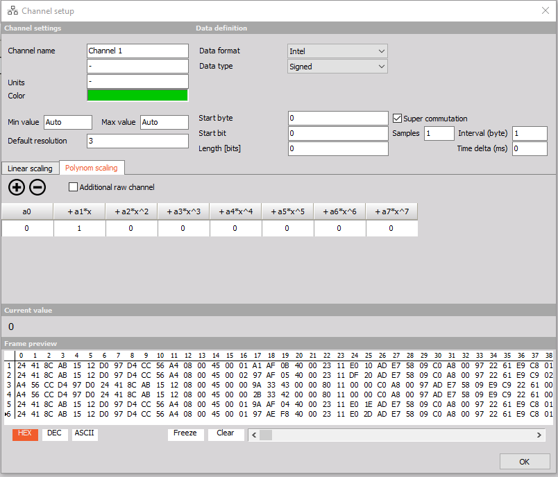
In this screen
- Channel name - Rename channel as required
- Data format - allows the choice of a signal by the available dropdowns of Intel or Motorola
- Description can be typed within the box below Channel name
- Data type - allows the choice of type by the available dropdowns (signed, unsigned, IEEE Float, MIL-STD 1750A)
- Units - specific engineering unit can be inputted here
- Color - by clicking this box pops up another dialog box that allows you to select a predetermined or custom color assigned to this parameter.
- Min value and Max Value - “Auto” typed in these boxes auto ranges the min and max for you. You can select these manually.
- Start Byte - This allows you to specify the Start byte
- Start bit - This allows you to specify the start bit
- Length [bits] - This allows you to specify the length
- Draft resolution - Default is set to 3, but is manually adjustable is you require
Two forms of Scaling are available within this section:
- Linear scaling - This will allow you to apply a direct scaling factor and/ or offset to your parameter
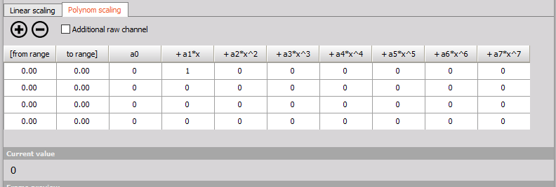
- Polynom scaling - Polynomial scaling will be applied here allowing the correction factors to be directly fed into the data system. Up to 7th order polynomials are available but if not required, simply placing a zero (0) within the unused areas will prevent an application of the respective power. A single poly scaling can be applied across the entire range but if a range for a factor is required, simply pressing the (+) sign adds in two more columns that specify a range for a specific polynomial as seen below.
No matter which scaling is chosen, the Current value box will show you the current value allowing a quick, in window reference.
Super commutation is accomplished by checking the box within the channel setup area. Three additional parameters will appear in which you will enter the required information such as samples, interval (byte), time delta (ms).
Synchronization: Masterclock mode
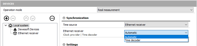
The data from the Ethernet stream can also be used as the master synchronization clock for DewesoftX measurements. To properly set this you must select “Ethernet Receiver” as the Time source in Local system settings (HW settings).
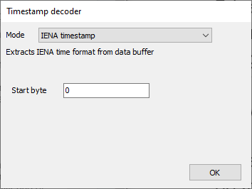
Each defined Filter Chain must have an absolute time option selected in the Timestamping options, which is currently only the INEA timestamp option. Additionally you must add the the Start byte, which represent the start byte of the time data.
Measurement
If the data channel is set to “Used” within the setup screen, we can now switch to the Measure mode.
Channels that are used in the setup screen are now usable similar to other channels such as analog inputs. The ethernet channels set to used are now available on the right-side area under the header in measurement mode
NOTE: Ethernet channels will be at an Asyncronous rate
FAQ
This section should help to find quick solutions for common problems.
Problem: If adding an Ethernet data stream in the plugin, the following error message appears: “Could not load wpcap.dll. Or if Data Source Setup is blank (imege below). Check if wpcap is installed.” ( WPCAP.DLL NOT FOUND PICTURE)
![]()
Solution: WinPcap has to be installed first. http://www.winpcap.org/ See also point 1.5 “WinPcap Installation”.
Problem: Ethernet Channels are not present within the Measurement screen
Solution: Ensure the channel is “used” within the ch. setup screen, ethernet receiver plugin, and under the appropriate feeds.
Problem: How do I collect all ethernet data coming across a stream?
Solution: In the filter settings, under enabled channels, the option for Filtered frame. By checking this box, a data channel will appear within the export named “data”. Use this channel and export as you see fit to view ALL the ethernet data with time stamps that occur when the data is collected by the NIC card.
Version History
Version history is retained by DewesoftX and is accessible via software changelogs to include module change history and documentation version.