Frequency domain filter
When you press the Setup button on new activated FFT Filter line, the following FFT filter setup window will open:
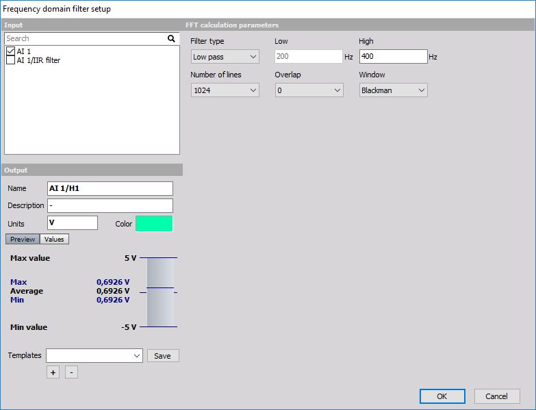
The filter supports multiple input channels.
For detailed information about basic settings of the input and output channels see -> Setup screen and basic operation Math.
FFT filter description
FFT filter is quite different to other types of filters. While IIR and FIR filters are time domain filters, FFT filter calculates the spectrum of the signal with specific number of lines and overlap and then extracts the RMS value of certain range of this signal. Therefore the result is not the full curve, but only one value per frequency spectrum.
The usage of this filter is to extract low peaks of signals where there are big harmonics nearby where it wouldn’t be possible to choose IIR filter which would extract this low amplitude.
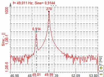
The example below shows the electromotive winding failure which can be seen as low values at the rotation frequency where the line frequency is very high:
We can design our own filter -> see -> Custom FFT Filter.
FFT filter parameters
To set the FFT filter, it is recommended to observe the signal in the FFT display and choose the right Number of lines and Window which fits the best and then set the filter parameters.
For FFT Filter you can set:
FFT calculation parameters
Amplitude extraction parameters
only for fixed frequency source
only for tracking frequency source
only for Tracking Frequency source
Number of lines
You can select Number of lines from the list.
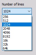
This defines the resolution of the filter as well as the number of points in the calculation. The resolution needs to be high enough that the wanted harmonic can be clearly extracted, but not too high to have a higher result update.
Overlap
You can select Overlap from the list.
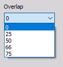
Overlap defines (same for FFT averaging) how many ‘old’ data is taken for next calculation. This increases the result update rate with the same number of lines.
Window type
You can select Window type from the list.
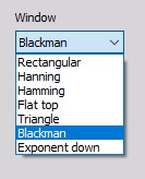
The window defines the behavior of the filter in the transition and the stop band (the height of the sidebands and the width of the main band).
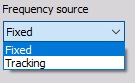
Frequency source
You can select Frequency source from the list if Tracking filter type is enabled:
Fixed - Fixed frequency will always take fixed value for center frequency.
Tracking - Tracking frequency means that the center frequency will depend on a second input channel (for example rotation frequency).
If the frequency source is external, we can define the channel where the frequency is defined and the filter will change the characteristic to always filter correctly like in the time domain. This is especially useful for example for CA noise calculation on the external clock.
Delta frequency
In this field, you can enter Delta frequency in Hz. This value depends on the wanted frequency band. It also depends on the window and number of lines (line resolution). In our example we would choose 0.5 Hz since we don’t want that 50 Hz value will appear in the result.
Center frequency
If we choose Fixed Frequency source, we need to enter Center frequency in Hz. The center frequency is the middle value of frequency for value extraction. In our example above we would take 49 Hz as the center frequency.
Filter settings for Tracking frequency source
If we choose Tracking Frequency source, we need to enter the Frequency channel and Number of harmonics instead of Center frequency:
![]()
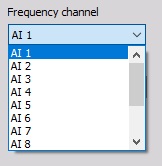
Frequency channel
Frequency channel is the channel with the current frequency which needs to be extracted. The unit of this channel must be in Hz.
Frequency channel can be selected from the list:
Number of harmonics
Number of harmonics describes how many harmonics need to be extracted from the spectrum. If we enter a value of 5, there will be 5 channels created for each input channel. The first channel will have the center frequency as the frequency channel; second will have twice the frequency of the input and so on.
Custom FFT filter
If Custom filter is selected from the Filter type, then we can design our own filter. With this option, we can create any type of filter curve in the frequency domain and calculate the RMS value or the filtered time signal.
Sometimes it is not easy to define filter characteristics in the time domain, but here we can have it defined in the frequency domain. Custom FFT filter is perfect for such case.
Since the overlap-add method is equivalent to a FIR filter, this custom filter has now also a phase change option. The phase can now be set manually between the input and the output signal.
There are also two options to preview axis type where the axis scales can be previewed as linear (Lin-Lin) or logarithmical (Log-Log).
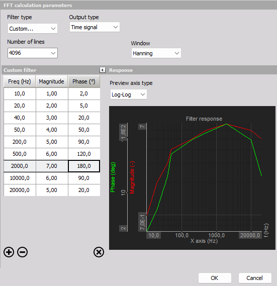
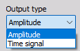
When setting the Filter type to “Custom…” the Output type can be set to either:
- Amplitude - RMS values, one for each filtered spectrum.
- Time signal - filtered synchroneous time sample values.
Amplitude
Setting the Output type to Amplitude will result in having one output RMS value for each time block used for the frequency spectra. The required block length is dependent on the used Number of lines. Increasing the Number of lines will also increase the time block length and hereby reduce the output rate of RMS values.
Time signal
The Output type “Time signal” performs signal processing and inverse FFT (IFFT) in a way such that the output time data is the frequency filtered version of the input time data, sample-by-sample. The filtered IFFT time signals can then simply be further processed and analyzed as time synchronous signals.
The method used for the custom IFFT based filter is referred to as the ‘Overlap-add method’. The overlap-add method is equivalent to using a custom FIR filter, but it is more efficient in case of a large number of filter taps. A large number of taps is required to achieve a desired frequency response of the filter. Generally more taps (or FFT lines in case of this IFFT based filter) will approximate the frequency response more closely.