Standard filter
Standard filter basically allows high, low, band pass and band reject filters.
With Filter option on IIR Filter settings section you can set:
You can see the effect of these settings directly on Response curve /Zeros & Poles display for Filter Type: Low pass, High pass, Band pass, Band stop and different Prototype.
Type of Filter
You can select Filter type from list between:
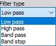
- Low pass - Low pass filters cut the high frequencies of the signals.
- High pass - High pass filters DC and low frequencies.
- Band pass - Band pass filter filters high and low frequencies, so there is only one band of values left.
- Band stop - Band stop filter filters only one section of frequencies.
Prototype of Filter
You can select Prototype of Filter from list between:

- Butterworth - Butterworth is without the ripple and maintains the shape with higher orders. Roll-off is defined with $(-20 \frac{dB}{decade} \times order)$. It is also known as maximally flat magnitude, suggesting that the filter response is really flat in the pass band.
- Chebyshev - Sometimes the selection of the filters is defined by the application, but in general, the Chebyshev has a highest roll-off of all three, but has a ripple in the pass band and doesn’t maintain the shape with higher orders.
- Bessel - Bessel filter is the filter with maximally linear phase response. The roll off however is the least step of all three filter types.
Order
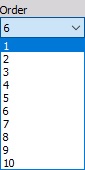
You can select Order from the list. The order of the filter defines the steepness of the filter. For the Butterworth the roll-off is $(-20 \frac{dB}{decade} \times order)$, so for the sixth order, the roll-off would be $-120 \frac{dB}{decade}$. That would mean if the amplitude at 100 Hz (already in the stop band) is 1, the amplitude at 1000 Hz would be $1E^{-120/20}=1E-6$.
The highest as the order is, more calculation power will be needed to calculate the filter. We need 6 multiplications for every two orders of the filter.
Cut-off frequency
The filter cutoff frequency defines the -6 dB point (half amplitude) of the filter. You can enter Cut-off frequency in field:
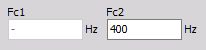
- Fc1 - Low frequency
You can enter Fc1 for Low pass, Band pass and Band stop filter.
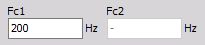
- Fc2 - High frequency
You can enter Fc2 for High pass, Band pass and Band stop filter.
- Both High and Low frequency
You can enter Fc1 and Fc2 for Band pass and Band stop filter.
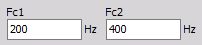
Fc1 value must be always lower than Fc2. These values are limited by filter stability. In Dewesoft the filters are calculated in sections, which enable the ratio between cutoff and sample frequency in a range of 1 to 100000. So we are able to calculate 1 Hz high pass filter with 100 kHz sampling rate.
Ripple
You can set also Ripple. Ripple is the maximum amplitude error of the filter in the pass band in dB.
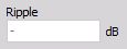
NOTE: This field appears only for Chebyshev filter Prototype.
Scale
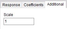
For filters, you can enter also Scale. Scale factor means the final multiplication factor before the value is written to the output channel. It helps us to change the unit, for example. A good example of using the Scale is shown in the Integration section.
Response curve / Zeros & Poles preview
On the lower side, we see some useful information of the chosen filter. First is the response curve.
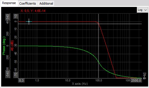
The red graph shows the amplification/attenuation of the filter in dB related to the frequency. To refresh the memory, dB scaling is calculated with equation $a [dB] = 20 \times log_{10}(A)$, so the attenuation ratio is calculated with $A=10^\frac{a}{20}$.
If we read out the value of -34 dB as attenuation, the ratio between input at output at that frequency will be A=10^(-34/20)=0,02. So if the input is 1 V sine wave, the output will be 0,02 V sine wave.
The phase shows the delay of the signal in degrees.
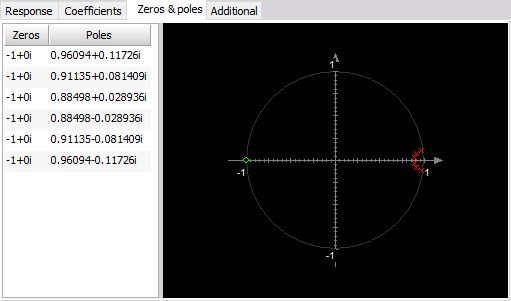
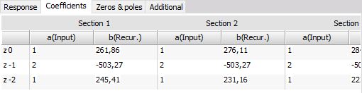
Lower table shows the coefficients with which the filters will be calculated. The filter is split into several sections for increased stability, so the result from the first section is taken to the next section and so on. These coefficients can be also copy / pasted with a right mouse click on the table to be used from/in other calculation programs.
On Response curve preview you can choose between Logarithmic and Linear display, you can also edit coordinates value and auto scale Y axis.

Zeroes & poles diagram shows the position of filter zeroes and filter poles and can suggest the stability of the filter.