Sine processing (COLA)
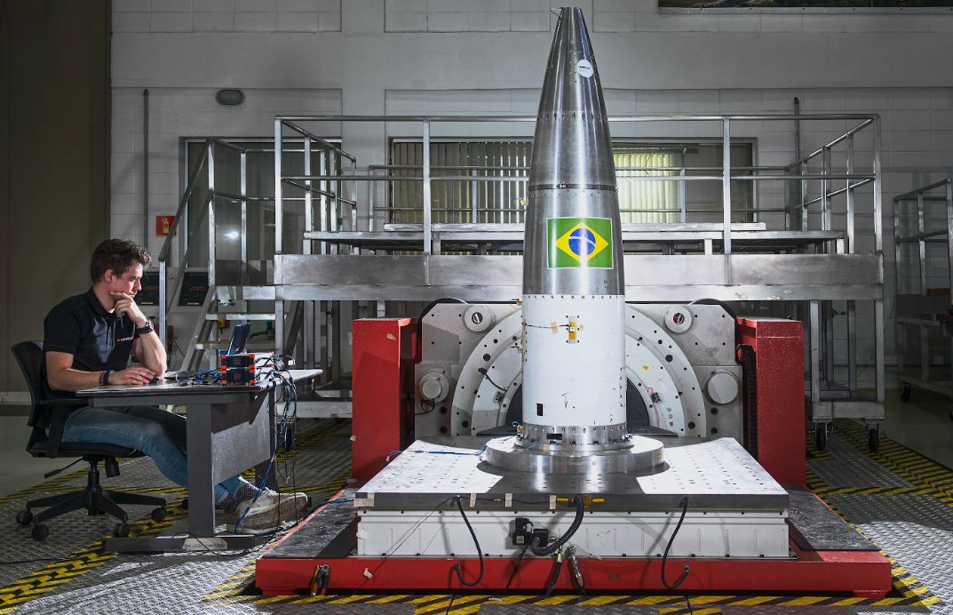
Sine Processing can be used for analyzing a system being excited sinusoidally, for example a structure being excited by a shaker system as illustrated below:
The Sine processing module builds up spectra over a selected range of excited sinusoidal frequencies. As the excitation sine signal is sweeping over specific spectral lines the related magnitude and phase information for those lines are determined.
When adding a Sine processing module to the Setup the following module setup window will appear:
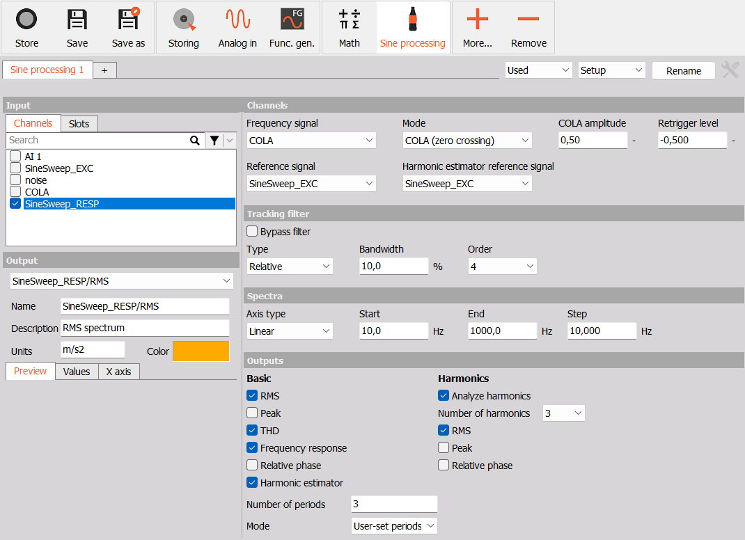
The Sine processing module continuously measures the input signals and relates the data to the measured Frequency signal data, hereby the output spectra gets build-up as the sinusoidal excitation signal is sweeping over the spectral frequnecy range.
For some output types like the Transfer function and the Harmonic estimator the module also calculates a single line DFT (Discrete Fourier Transform), which follows the sinusoidal excitation component by tracking the Frequency signal.
When the single line DFT is used the amplitude and phase information are extracted over a number of sine-periods for each spectral line.
An example of a user-defined Measure display, designed for Sine processing measurements, is illustrated below.
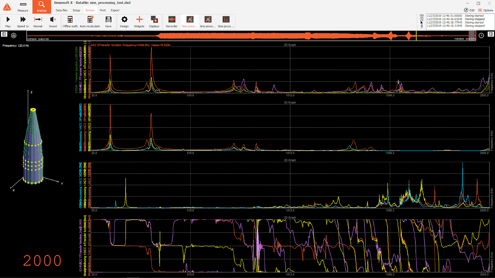
In the Measure display illustration, the magnitude and phase values of Transfer functions are plotted across the frequency sweep range in 2D graph widgets while the actual sweeping Frequency signal value is shown with a Level meter widget. The structure under test is also shown and created with a Modal geometry widget.
Channels
Channels used to control the sine processing can be selected under this section.
Frequency signal
The Sine processing Frequency signal is the tracking signal which the DFT is relating to. It supports both the use of raw Analog Input signals, and COLA (Constant Output Level Amplitude) signals e.g. from vibration controller devices.

NOTE: The Frequency signal must include information relating to the fundamental sinusoidal frequency, which the structure under test is excited with.
Reference signals
The Sine processing supports output channels that include phase information. The phase information is determined relative to reference signals.
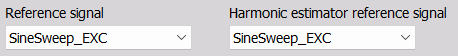
When the Frequency response output channel is enabled the phase data will be relative to the selected Reference signal.
When the Harmonic estimator output channel is enabled the phase data will be relative to the selected Harmonic estimator reference signal.
Tracking filter
A tracking filter can be used to remove energy that does not correlate with the sinusoidal Frequency signal.
The Tracking filter can be relevant for the output channels RMS, Peak, and THD since these values are calculated based on the energy over the full frequency range of the input data.
The Tracking filter can be set to be bypassed, and hereby such filter will not be used for the Basic outputs. The Harmonic output types will still use such tracking filters to be able to relate spectral content to specific harmonics.
Filter Bandwidth
A Band-Pass filter can be applied with a Bandwidth defined either Relative or Absolute (Fixed)
![]()
Relative - let you set a band-pass filter width with a certain percentage relative to the variable sinusoidal frequency.
Fixed - let you set the band-pass filter width with an absolute frequency width which will be used across the full sine-sweep frequency range.
Filter order
The Tracked band-pass filter order can be set between 2 and 10. Increasing the filter Order will increase the attenuation strength for energy components laying outside the BP-filter. For each Order number the tracking filter will attenuate 20 dB per decade, e.g. 80 dB per decade for a 4th order filter.
NOTE: For the Harmonic estimator and Frequency response output channels a tracking filter is already applied since the result data only relate to the exact frequency of the Frequency signal, due to the single line DFT calculation method used.
Spectra
In this section the frequency axis of the output spectral results are defined.
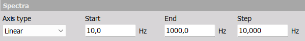
The Axis type can be set to have the spectral line spacing set either Linear or Logarithmic.
The Start and End parameters determine the lower and upper frequency of the spectral frequency axis.
The Step parameter defines the spectral line spacing.
- If the Axis type is set to Linear the Step is set with a fixed frequency width, delta freq., in Hz.
- If the Axis type is set to Logarithmic the Step is set with a frequency width that increases logarithmically with the axis, and which has a spectral line spacing defined as a fraction of an octave.
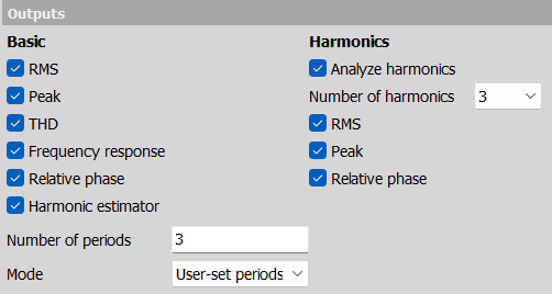
Outputs
The Sine processing module provides multiple outputs as listed below:
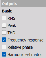
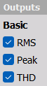
Basic
Basic output types
RMS - Root-Mean-Square spectrum. The spectral line values relate to the total RMS measured in the time domain at the instance where the Frequency signal was located around the specific line frequency.
Peak - Peak spectrum. The absolute maximum value of the signal detected in the time domain at the instance where the Frequency signal was located around the specific line frequency.
THD - Total Harmonic Distortion spectrum, is calculated as the Total Harmonic Distortion + Noise (THD+N). It is based on the RMS ratio between harmonics + noise and the fundamental at the instance where the Frequency signal was located around the specific line frequency.
Frequency response - Transfer function spectrum. This is based on the ratio between the structural output response- and the excitation input’s magnitude and phase.
A single line DFT, based on the Frequency signal, is calculated for the structural excitation and response signals. The complex ratio between them provides the Frequency response result.
The excitation signal used is the selected Reference signal.Relative phase - Phase spectrum. The Relative phase spectrum is calculated similar to the Basic Frequency response output, but the amplitude is normalized to unity. Having this complex phase spectrum channel selected in a 2D graph widget lets you decide which phase format you want to use.
Harmonic estimator - Tracked Phase-referenced spectrum. The Harmonic estimator uses a single line DFT that tracks the Frequency signal to determine the absolute peak amplitude across the set Number of periods. The phase is relative to the set Harmonic estimator reference signal.
Harmonic estimator settings
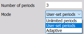
Number of periods
If the Mode parameter is set to User-set periods then the Harmonic estimator spectral line values are each determined over the set Number of periods.
Mode
Unlimited periods - The Harmonic estimator spectrum values are determined over as many periods as available for each line frequency. There might be some limitations depending on how long the signal is at particular frequencies.
User-set periods - The Harmonic estimator is determined over the set Number of periods.
Adaptive - The Harmonic estimator is determined over a variable number of periods, but at least one period. 1 period is used up to 25 Hz and then thereafter the number of periods increases as the Frequency signal increases in frequency.
Harmonics
Analyze harmonics - Enables spectral outputs with values relating to specific harmonic components.
Such harmonic spectral results will be produced for those Hamonic output types which have been checked on: RMS, Peak, and Relative phase.Number of harmonics - A spectrum will be produced for each harmonic and for each output type which has been checked on.
For example, if Number of harmonics is set to 3 then spectra are calculated which relate to the 2nd, 3rd and 4th harmonic. The 1st harmonic (the fundamental) is already determined under the Basic output section for similar output types.
NOTE: Harmonic outputs will always use a tracking filter with the band-pass centered around the specific harmonic. The BP-filters will use filter settings as specified under the Tracking filter section.
Harmonic output types
The Harmonic output spectra RMS, Peak, and Relative phase is determined similar to the Basic outputs of the same type, but here first the Tracking filter is bandpass filtering the harmonic content. Hereby the harmonic outputs only relate to the specific harmonic content.