Trigger condition setup
Dewesoft offers several different trigger conditions, which can be set on Condition setup window. Trigger conditions can be combined completely independent, that combined with an OR function. That means any defined trigger condition has to become true to activate the trigger.
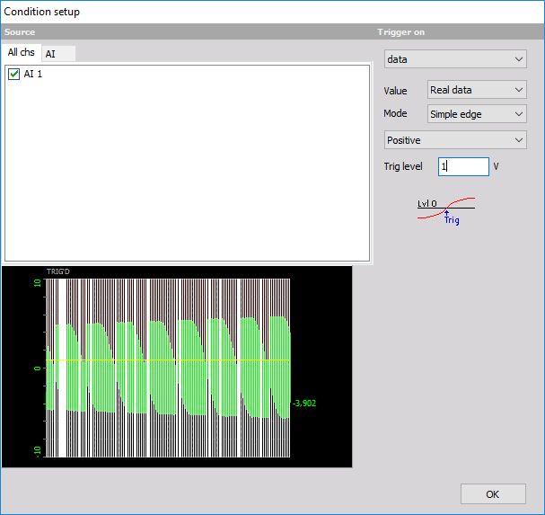
When we select the Setup button on the Dewesoft Setup screen - trigger condition line, the following Condition setup window appears:
Choose the trigger condition according to your requirements and press the OK button to accept the trigger settings.
In Condition setup window we can enter all the trigger condition settings. Source section on screens left side and in upper part available Channels are displayed in two tabs:
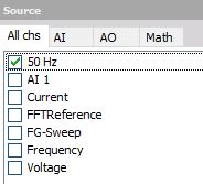
- All chs - all channels
- AI - analog input channel
First of all, you have to select the desired channel out of the All chs / AI tab list. It displays all available channels. To select channel click on it. Selected SOURCE is surrounded with dashed white line and box before channels name is crossed.
In the lower part, the current signal value is displayed. The white lines displayed to indicate when the trigger condition became true.
Trigger on - on the screens right side are fields to set up trigger; this fields depends from selected trigger type; below trigger settings symbolic trigger curve is displayed.
Trigger type
The following trigger types can be used as a trigger input
- Data
- Time
- FFT
Data trigger setup
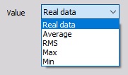
- Define the Value - When the data trigger is selected, you can also choose between Real data, Average, RMS, Max and Min from the drop-down list for your trigger condition. The Average, RMS, Max and Min values are taken from the Static acqusition rate (Reduced rate) data.
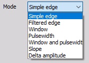
- Define the Mode - Select the trigger type Simple edge, Filtered edge, Window, Pulse-Width, Window and pulse-width, Slope or Delta amplitude from the drop-down list.
- Setup other trigger condition - These settings (e.g. Slope, Trigger level, Rearm level, Pulse time…) depend on the selected trigger type in Mode field.
Trigger Mode and setting
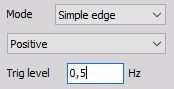
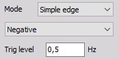
- Simple edge - This is the most used trigger condition with data acquisition systems. The trigger event is a rising or falling edge, which crosses a defined level.
Positive slope:
Negative slope:
Trigger on rising edge when the signal rises over defined Trig level.
Trigger on falling edge when the signal drops bellow defined Trig level.
Symbolic display of trigger condition (below settings):


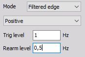
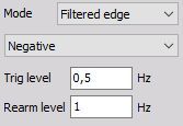
- Filtered edge - This is basically the same as the simple edge trigger, except for the rearming level. This level can be used to define a second level, which must be crossed before the trigger condition can become true again. This trigger type is mostly used with very noisy signals.
Positive slope:
Negative slope:
Trigger on rising edge when the signal rises over defined Trig level; re-triggers only when Rearm level has been crossed.
Trigger on falling edge when the signal drops bellow defined Trig level; re-triggers only when Rearm level has been crossed.
Symbolic display of trigger condition (below settings):
- Window - works with two independent levels, which build some kind of window. The trigger condition can become true when the signal enters or leaves the window.
Enter range:
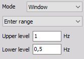
Trigger when the signal enters the window - signal falls below Upper level or rises above Lower level.
Leaves range:
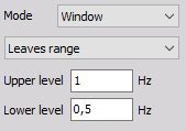
Trigger when the signal leaves the window - signal rises above Upper level or falls below Lower level.
Symbolic display of trigger condition (below settings)


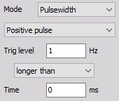
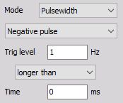
- Pulse-Width mode
Longer than Time - checks in addition to the level (like the simple edge trigger) the duration Time of the event and triggers only if the event is longer above the selected level
Positive pulse - Trigger on rising edge when the signal rises over defined Trig level and stays above this level longer than selected Time.
Negative pulse - Trigger on falling edge when signal drops bellow defined Trig level and stays below this level longer than selected Time.
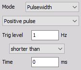
Shorter than Time - checks in addition to the level (like the simple edge trigger) the duration Time of the event and triggers only if the event is shorter above the selected level.
Positive pulse - Trigger on rising edge when signal rises over defined Trig level, but falls below this level earlier than selected Time.
Negative pulse - Trigger on falling edge when signal drops bellow defined Trig level, but rises above this level earlier than selected Time.
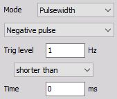
Symbolic display of trigger condition (below settings):


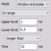
- Window and Pulsewidth condition combines the features of the window and the pulse-width trigger; it is very powerful, but you really have to know what you expect to trigger on.
Longer than time (level in range) - Trigger when the signal enters the window (signal falls below Upper level or rises above Lower level) and stays inside for a longer than defined Time.
Longer than time (level out of range) - Trigger when the signal leaves the window (signal rises above Upper level or falls below Lower level) and stays outside for a longer than defined Time.
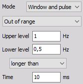
Symbolic display of trigger conditions:


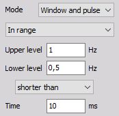
Shorter than time (level in range) - Trigger when the signal enters the window (signal falls below Upper level or rises above Lower level) but leaves before the defined Time is over.
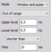
Shorter than time (level out of range) - Trigger when the signal leaves the window (signal rises above Upper level or falls below Lower level) but returns before the defined Time is over.
Symbolic display of trigger condition:


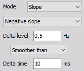
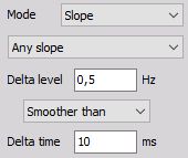
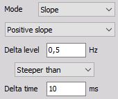
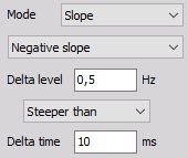
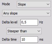
- Slope mode
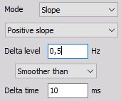
Smoother than Delta time (positive slope) - Triggers when signal rises over defined Delta level later than defined Delta time.
Smoother than Delta time (negative slope) - Triggers when signal drops below defined Delta level later than defined Delta time.
Smoother than Delta time (any slope) - Triggers when signal rises over or drops bellow defined Delta level later than defined Delta time.
Symbolic display of trigger condition:


Steeper than Delta time (positive slope) - Triggers when signal rises over defined Delta level earlier than defined Delta time.
Steeper than Delta time (negative slope) - Triggers, when signal drops bellow, defined Delta level earlier than defined Delta time.
Steeper than Delta time (any slope) - Triggers, when signal rises over or drops bellow, defined Delta level earlier than defined Delta time.
Symbolic display of trigger condition:


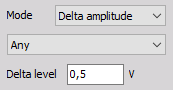
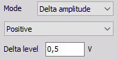
- Delta amplitude mode
Any slope - the trigger event in this mode appears every time the amplitude of the trigger channel increases or decreases for the defined delta level
Positive slope - Triggers every time the signal increases or decreases over the defined Delta level.
Negative slope - Triggers every time the signal increases over the defined Delta level.
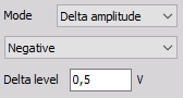
Triggers every time the signal decreases over the defined Delta level.
Symbolic display of trigger condition (below settings)

Time trigger setup
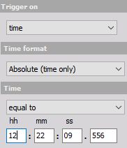
Absolute (time equal to) - The system triggers exactly at the defined time hh:mm:ss.xxx (also every day if the time matches).
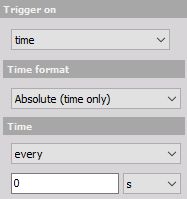
Absolute (every) - The system triggers every defined time x (unit), the time starts running from the beginning of the measurement.
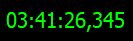
Displayed time:
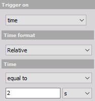
Relative (time equal to) - The system triggers when the defined time x (unit) has been passed since the measurement has been started.
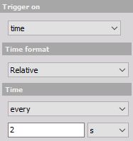
Relative (every) - The system triggers every time x (unit), the time starts running from the beginning of the measurement.
Displayed time:
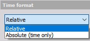
Time format selected from the drop-down list:
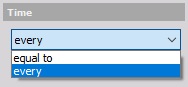
Time selected from the drop-down list:
Units selected from the drop-down list:

FFT trigger setup
Up to now, we triggered the system only on amplitude values over the time and/or directly on time. The FFT trigger allows us to trigger on amplitude values in the frequency domain!
This type of trigger is very helpful in any kind of dynamic applications where you want to supervise the frequency behavior of the system under test.
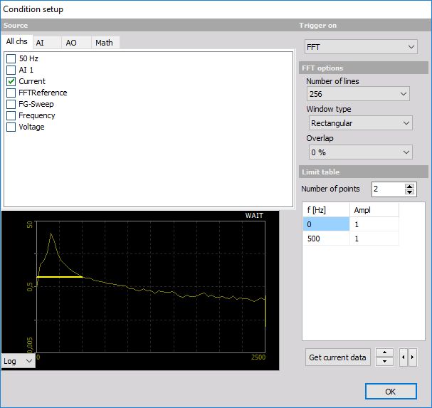
FFT options
To trigger on frequency changes you have to define the FFT options to get a useable result to trigger on:
- Number of lines (256 to 64k),
- Window type (Rectangular, Hanning, Hamming, Flat Top, Triangle, Blackman and Exponent down) and
- Overlap (0, 25, 50, 66 and 75%)
For information about Number of lines, Window type and Overlap see —> FFT analyser
For background information about FFT analysis see —> Frequency domain analysis
NOTE: Preview at the left bottom area shows the change effects on the FFT immediately. On this display can be select beside Logarithm (see display above) also Linear display.
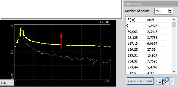
Limit table
After you have done your FFT option settings you have to define:
Number of points (limits on Limits table)
The limits - Ampl. levels for f [Hz] on Limits table.
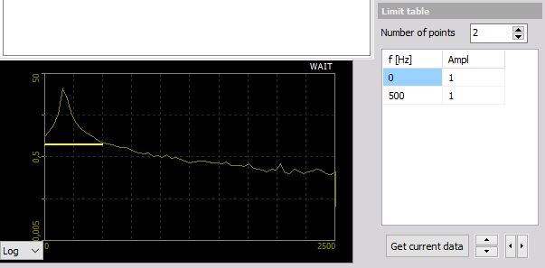
Default (standard) Number of points are 2. The standard Ampl. level is 1 for 0 and max. frequency. You can click on this field and change this value.
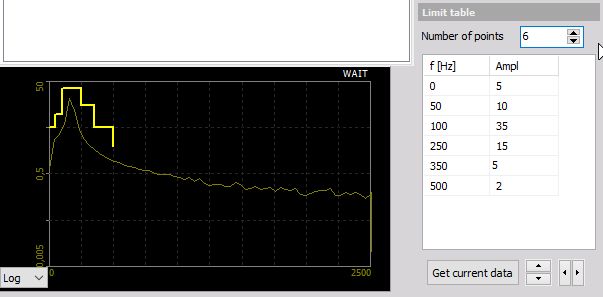
You can increase Number of points to expand the table:
You can now define the limits in two ways:
- Enter the values manually - When you enter the values manually into the table, you normally take just a view points to define the frequency mask.
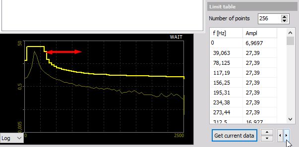
- Take the current measurement from the system - The second way is to take a frequency mask out of the currently displayed signal. To do that simply presses the Get current data button. The currently calculated FFT will be stored as a mask and displayed both on the preview display and in the table at the left bottom.
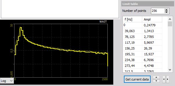
Now you can manipulate the mask by editing the table or - much faster -press the button to move the limit up/down or press the button to add/remove limit in the frequency domain.
Examples:
Frequency mask moved up:
Frequency limits widened: