Time ODS
Time ODS is used to animate and visualize structural deflections based on measured time data.
NOTE: All Input channels must have the same physical quantity, which has to be either: Displacement, Velocity or Acceleration.
For more information about Modal test take a look at the Modal test manual.
For more information about how to use the Geometry editor see: Geometry editor
Output settings
Output type
The Output type defines the physical quantity of the output response channels. The user can select between:
- Displacement
- Velocity
- Acceleration
If the physical quantity of the Input channels is different from the selected Output type, then the Input channels will be converted to have the Output type. For example, If the Input channels have acceleration as their physical quantity, and the Output type is set to Displacement, then the input channels will get double integrated in order to convert them to represent displacement.
Output unit
The Output unit defines the unit of the output response channels. Based on the selected Output Type, the user can select between a list of related units. The list of related units can be edited in the Physical Quantity Editor. The default list of units are shown below:
Displacement
- m (meters)
- km (kilometers)
- dm (decimeters)
- cm (centimeters)
- mm (millimeters)
- um (micrometers)
- in (inches)
- ft (feet)
- yd (yards)
- mi (miles)
- nmi (nautical miles)
Velocity
- m/s (meters per second)
- mm/s (millimeters per second)
- km/h (kilometers per hour)
- mph (miles per hour)
- knot (nautical miles per hour)
- ips (inches per second)
Acceleration
- m/s2 (meters per second squared)
- g (gravitational acceleration)
If the selected Output unit is different from the Input channel unit then value scaling will be performed - converting the input unit to the desired output unit.
Filter low frequencies and DC and Filter high frequencies
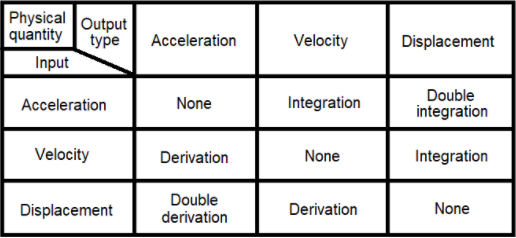
If the physical quantity of the Input channels is different from the selected Output type, the required physical quantity conversion is done by time integration/differentiation filters.
Which time filters are required for the different conversions are illustrated in the table below.
If integration filters are required for conversion then the checkbox ‘Filter low frequencies and DC’ will be available.
Time integration and double integration will amplify lower frequency components. If such lower frequency components only consist of irrelevant noise the user has the ability to remove those components by enabling the ‘Filter low frequencies and DC’ checkbox.
If derivation filters are required for conversion then the checkbox ‘Filter high frequencies’ will be available.
Time derivation and double derivation will amplify upper frequency components. If such upper frequency components only consist of irrelevant noise the user has the ability to remove those components by enabling the ‘Filter high frequencies’ checkbox.
Filter order
The Filter order determines the strength of the filters used to cut-off either the low frequencies and DC or the high frequencies, depending on which time filter is required to obtain the desired Output type.
The Filter order can be set from 1 to 10 and the frequency cut-off slope will be approximately 20 dB per order.
Cut-off frequency
The Cut-off frequency determines at which frequency the filters for Filter low frequencies and DC or Filter high frequencies will begin to cut-off the output signals with a rate/strength defined by the Filter order.
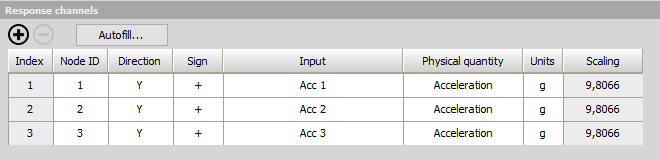
Response channels
The Response channels table, found under the Reponses tab, defines and connects DOF information and Input response channels.
DOF information defines node point locations and directions to measure. Such DOF information are added to the measured Input response channels enabling the response channels to be proper visualized on geometry animations.
Index
The index is only used to help with overviewing the Response channels table, e.g. when having a large amount of channels. The Index numbering will start from 1 and increase up to the number of response channels added.
Node ID
The DOF Node ID is a number that relates to the physical location of the selected Input response sensor. The Node IDs are also used when creating a geometry animation, (See the section: Geometry editor. Hereby the node points on a geometry and the response Node IDs are mapped together, such that geometry animations can reflect the measured characteristics.
Direction
The Direction defines in which directions (x, y, z) measurements were performed for related DOFs and Node IDs. The selected Directions are also used for geometry animations to reflect measured deflections in the correct directions.
Sign
The Sign defines the orientation (+, -) of the DOF for the specified Direction. The Sign should reflect orientation of the related response sensor.
Input
The Input determines which Input response channel that is related to the specified DOF information (Node ID, Direction and Sign).
Physical quantity
Indicates the Physical quantity of the Input response channel. Changes to the Physical quantity of Input response channels are global changes and will affect all usages of the related channels.
The Input Physical quantity has to be either Acceleration, Velocity or Displacement.
If the Physical quantity is different from either Acceleration, Velocity or Displacement, then the related table cell will indicate ‘
Unit
Indicate the unit for the related Input response channel. Changes to the Unit of Input response channels are global changes and will affect all usages of the related channels.
Scaling
Scaling is a read-only parameter that indicates the Scaling factor that will be used in order to get correct values in the specified Output unit.
Autofill setup
By using Autofill multiple response channels can be added at the same time if the Input channels are AI (Analog Input) channels.
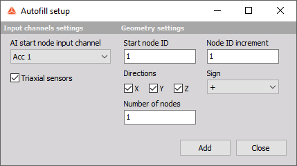
AI start node input channel
Defines the first AI channel to use as an Input response channel.
Triaxial sensors
A checkbox that indicates whether the used AI channels relate to uniaxial sensors or triaxial sensors.
If the checkbox is enabled then all used Directions can be selected and not only one.
NOTE: If you wish to use Autofill (for response channels) for triaxial sensors you must connect the response channels (Triaxial accelerometers) in a manner of: 1st sensor X, Y, Z, 2nd sensor X, Y, Z, and so on.
Start Node ID
Defines the starting point Node ID of the structure
Node ID increment
Sets the increment by which the Node ID number will advance from one DOF to the next.
Direction(s)
Select the direction(s) of the measurement (if Triaxial response you can select multiple).
Sign
Defines if the excitation will be positive or negative regarding the Direction.
Number of nodes
Defines the number of nodes to autofill. For example, if 2 nodes are selected to be autofilled and all Directions (X, Y and Z) are selected then 2 * 3 = 6 responses are added.
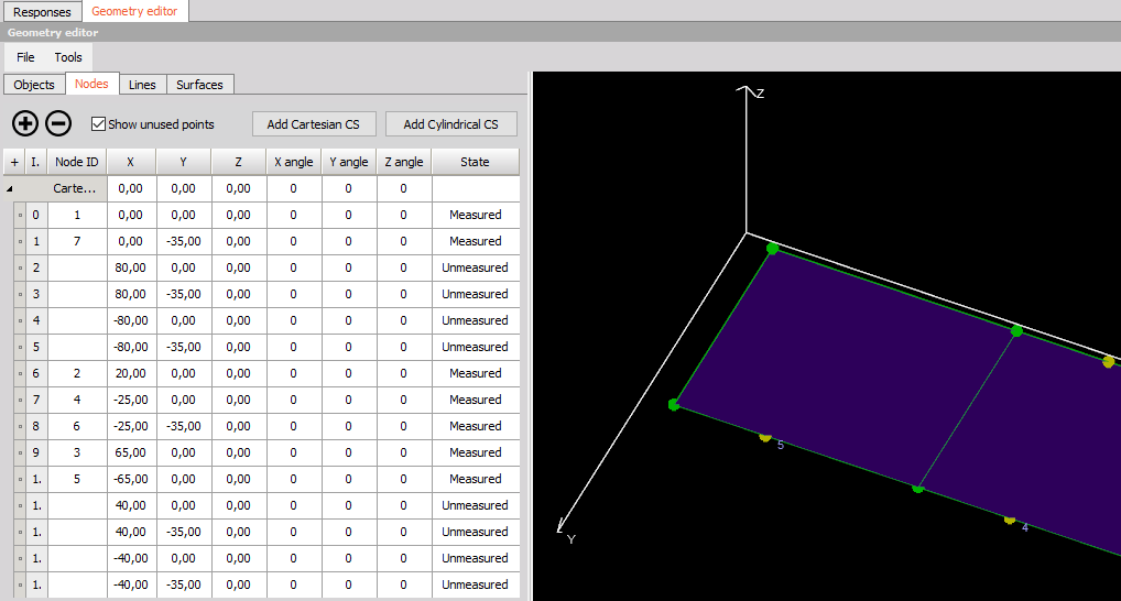
Geometry editor
Under the Geometry editor tab you can create or import a geometry with Node IDs that links to the measured response channels. For more information about how to use the Geometry editor see: Geometry editor