Result Definition
After selecting Result definition tab, the following setup screen is displayed:
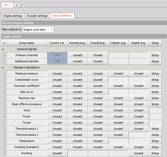
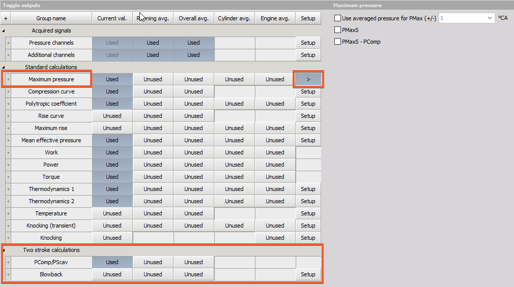
Outputs
You can can get different outputs from the CEA:
- Acquired signals group:
Standard calculations group:
Output Types
You can select different Output type as well:
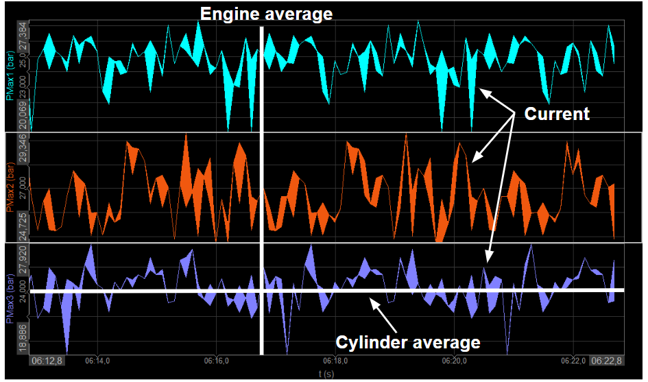
- Current Value - values calculated from the current pressure curve, for each cylinder individually calculated from the average
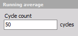
- Running average - Running average cycles calculate the mean value of the last n cycles. This basic statistic is calculated both for pressure and for the Additional channels of each cylinder. The result is a vector with the angle as a reference.
- Overall average - values calculated from the average pressure curve of all cycles since start of measurement, for each cylinder individually
- Cylinder average - gives one average vector for each cylinder separately for the complete measurement
- Engine Average - calculates the current average value of all cylinders together
Note the difference between current value, running average, and overall average from cylinder average and engine average: current value, running average, and overall average all first construct the pressure curve from the past however many cycles, and then calculate the output values with those curves as input. On the other hand, cylinder average and engine average don’t construct pressure curves, but instead take the average of the already calculated values based on current value’s pressure curve. This is also why cylinder average and engine average calculations don’t have resampled curves as output.
Results common settings
Align ouputs to:
- Engine cycle start
This setting will allign all calculated results to start of the engine cycle.
- Cylinder cycle start
This will aling the cylinder calculations to cylinder cycle start.
Outputs Explained
Pressure channels & Additional channels
Both Pressure channels and Additional channels located under Acquired signals group are primary outputs from the CEA and their current value is needed for further calculations. That is why they are by default defined as Used channels as well. You can additionaly define also other Output Types to them.
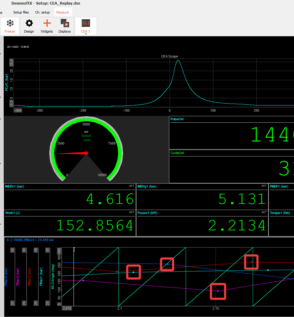
Maximum pressure
- Maximum pressure calculates the peak pressure of each cycle and angle of the peak pressure:
- Output is a single value once per cycle:
- PMax_X_ [bar] - maximum pressure of the cylinder X
- APMax_X_ [°CA] - angle of maximum pressure of cylinder X
- Output is a single value once per cycle:
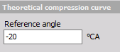
Compression curve
- Compression curve calculates the theoretical compression curve without combustion. Reference angle needs to be set to fit the compression curve with angle set at compression, before any ignition is present.
- Output is an array channel - PCom_X_ [bar].
- Output is an array channel - PCom_X_ [bar].
Polytropic coefficient
- Polytropic coefficient can be detected as an output. Parameters for start and end of compression and combustion need to be set properly to get the correct output.
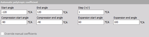
- Option Override manual coefficients allows you to override the manual coefficients and use the calculated output as an input for the Polytropic coefficients.
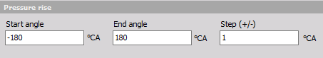
Rise Curve and Maximum Rise
- Rise Curve is a derivative of the pressure curve output as an array channel Rise X [bar/deg]
- Maximum Rise is output as a single value once per cycle.
The start-angle, the stop-angle and also the step size must be defined.
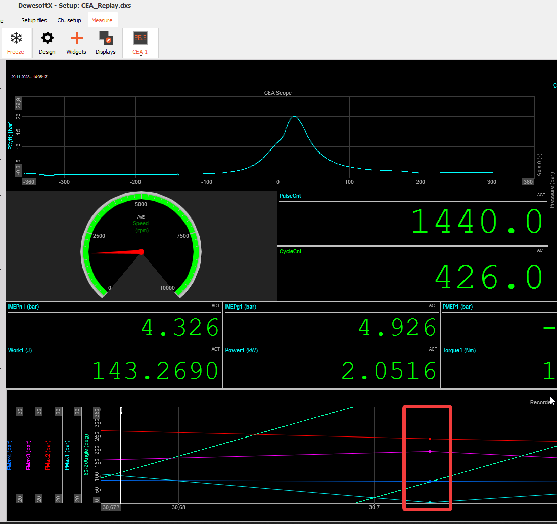
Mean effective pressure
- Mean effective pressure outputs a single value once per cycle:
- IMEPg_X_ [bar] - indicated mean effective pressure gross of cylinder X
- IMEPn_X_ [bar] - indicated mean effective pressure net of cylinder X
- PEMP_X_ [bar] - pump mean effective pressure of cylinder X
Work, Power, Torque
- Work, Power and Torque output a single value once per cycle:
- Work_X_ - [J]
- Power_X_ - [kW]
- Torque_X_ - [Nm]
Thermodynamic 1 & 2, Temperature
Thermodynamics 1 is the basic thermodynamic calculation that was implemented in the first CEA module and it was available in previous versions of Dewesoft X. Now it is basically only used for a relevant comparison in case you obtain some older results. While Thermodynamics 2 is an upgraded and advanced thermodynamic calculation algorithm that is now used as a primary tool for such calculations in Dewesoft X.
Thermodynamics 1 and 2 are performing the same calculations, except Thermodynamic 2 includes Temperature calculation as well.
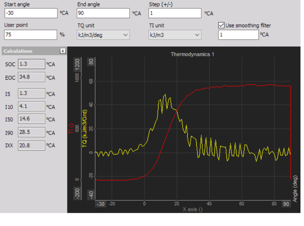
Thermodynamics 1 setup screen:
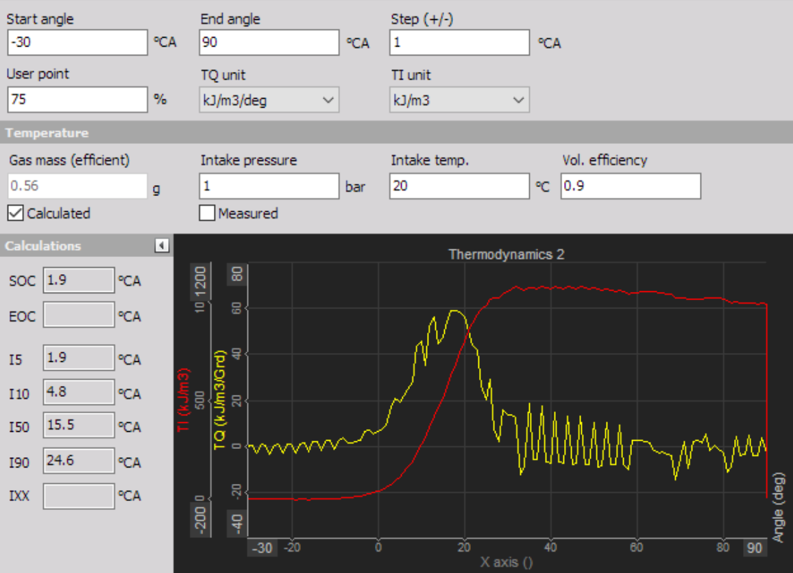
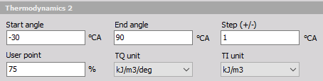
Thermodynamics 2 setup screen:
Settings and entered values for this Thermodynamic 1 & 2 CEA outpur are divided into 2 or 3 sections:
Thermodynamics 1 & 2 - are defining pressure derivative together with the Heat release.
- Start and End Angle [°CA] - For setting up the Heat release calculation the start and stop angle of the crank must be defined. The typical range is from -30° to +60°. An earlier injection start angle must be set according to the real injection point.
- Steps [samples] - The step input field defines the calculation width: e.g. Step 1 means the calculation is based on ±1 sample (or angle resolution value). A higher value smooths the result. For more information please refer to manual, chapter 11.4.1 Heat release TQ on page 80.
- User point [%] - Heat release creates several output channels with angle values for certain amplitude values - 5, 10, 50, and 90% (called I5, I10, I50, and I90). Additionally, we can define one user point called IXX where the XX is the percentage value of the heat release defined here.
- TQ and TI units - It is a unit for a heat release. We can either have the physical unit for the heat release or have it expressed in percentage:
- kJ/m³/deg - related work[kJ] to 1m³ per 1deg volume is related to Vs = swept volume
- % - scaled to sum of 100% (integrated signal =100%)
- Smoothing filter - is a property of Thermodynamics 1 only. It can calculate in the dependance on the moving average window of the defined °CA.
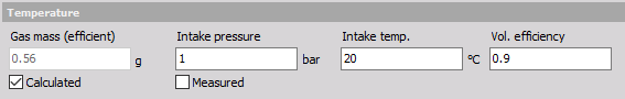
Temperature - included only in Thermodynamic 2.
- When you select Thermodynamics 2 calculation, the temperature will be selected as well - they are both related and have the same settings. The temperature inside the combustion is calculated based on the ideal gas law and is only valid at around TDC.
- Gas mass - For the Temperature calculation, the gas mass is required. This can be either manually entered, or calculated.
- Intake Pressure, Intake temp and Volumetric efficiency:
- If from Calculated is used, the intake temperature, intake pressure, and also the volumetric efficiency (0.9= 90% filled) must be entered.
- If Measured is selected, the intake pressure is measured from the zero point corrected high-pressure curve.
- When you select Thermodynamics 2 calculation, the temperature will be selected as well - they are both related and have the same settings. The temperature inside the combustion is calculated based on the ideal gas law and is only valid at around TDC.
- Calculation - displaying different calculated parameters.
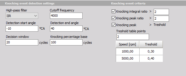
Knocking (transient) {#Knock(transient)}
After selecting Knock detection type CA following setup screen is displayed:

Knock detection is the principle for finding the amount of knocking due to late ignition. Settings and editable values for this Knock detection are:
- Knock detection (method Mannesmann VDO AG)
- Low-pass and High-pass filter
- In these fields, we define the Number of taps (according to angle resolution) of the average filter to cut low and high pass part of the signal.
- Noise threshold
- Is the value which defines the lower limit for calculation of values.
- Knock signal window width
- The width of the window on the left and right side of the pressure signal.
- Shift reference window
- Is two-point linear scaling offset definition of how much the calculation window is shifted for different speeds.
Knocking
Output channels: KP_Int (Knock Integral) - Delivers the integral of the superimposed, rectified knock oscillation. KP_PK (Knock Peak) - Delivers the absolute maximum of the rectified knock oscillation superimposed on the cylinder pressure. KP_EV (Knock Event) - Binary value (1/0) which indicates whether the current engine cycle was classed as knocking or not. KP_Frq (knock frequency) - Specifies the number of detected knocking cycles within the last ‘n’ cycles (‘n’ is predefined by user).
PComp/PScav {#PComp/PScav}
When a two stroke engine type is selected, some additional calculations are available. Maximum pressure calculation offers Maximum pressure Stroke and Compression pressure subtracted from maximum pressure Stroke.
PMaxS is the average of +/-5 samples from the maximum pressure at +- 0.1 deg angle resolution.
PMaxS – PComp presents the difference between PMaxS and the compression pressure. PComp is calculated from the compression curve function.
PComp (Compresion pressure) / PScav (scavenging pressure) calculation is dividing the PComp with the average scavenging pressure (PScav). PScav = Average at bottom dead center (-180deg) +/-20deg of all cylinders combined.
Blowback
Blow-back is the pressure difference when the piston top passes the scavenging port and the average scavenging pressure (E.g. +/-20° from BDC). The piston passes the scavenging port at the nominal blowback angle (NBA) with no shims. The apparent blowback angle (ABA) is the NBA + angle (considering the shims length).
User inputs for Blowback calculation:
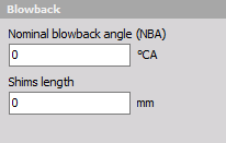
Blowback = Pressure(@ABA) - Pscav(+/-20° from BDC)