Microphone correction
The Microphone correction module is intended for noise measurement where corrections of sound pressure levels and spectral data must be corrected for the microphone response, system response, sound incidence angle, air absorption and many other corrections, allowing the test to adhere to the standards presuming such applied corrections when performing DUT (Device Under Test) noise measurements:
The Microphone correction plugin has been designed to run in parallel with the original microphone channels in order to easily monitor and analyze the differences between measurements with and without applied microphone corrections.
User workflow
The user workflow is created to follow all or a subset of the the general tasks listed below:
- Before
- System frequency response before
- Sensitivity calibration before
- Microphone response setup
- Environmental dependency setup
- Mic. distances, sound incidence and other custom correction setup
- DUT measurement
- Background measurement before
- DUT noise measurement
- Background measurement after
- After
- Sensitivity calibration after
- System frequency response after
Hereby the DUT (Device Under Test) can have the noise measurements performed with all related corrections taken into account, while also being compared to the original microphone measurements with no corrections.
Output result data
For each microphone used in the Microphone correction module, you will get a list of output results as indicated below:
- Total measured level - total RMS level, based on the related Octave spectrum
- DUT/Source noise spectrum - see Noise measurement
- Corrected Octave spectrum - see Spectral data
- Corrected FFT spectrum - see Spectral data
- System frequency response Before - see System frequency response
- System frequency response After - see System frequency response
- Sensitivity correction Before - see Sensitivity calibration
- Sensitivity correction After - see Sensitivity calibration
- Background noise Before - see Noise measurement
- Background noise After - see Noise measurement
Some of the results will be used in display widgets for monitoring and analysis, others are used in setup tables for signal correction processing.
Adding Microphone correction to a setup
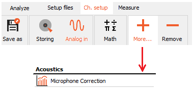
The Microphone correction module can be found under the Acoustics section in the list of modules to add when pressing the ‘More…’ button under Ch. setup:
After adding the module you will see a setup that is meant to be used for both different correction measurements and for DUT noise measurements with the measured corrections applied to it.
NOTE: All measurements will be performed under the Measure section after the setup has been completed.
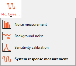
Measurement modes
Under General you must select which Measurement mode you are going to perform. Different related parameters will appear next to the measurement mode depending on which mode you choose:
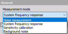
System frequency response
System frequency response is used to measure and correct for the system transfer function - the connection line from the start of the sensor cable to the acquired data samples.
Such system response correction measurements are done by exchanging the microphones with a signal generator that sends out a known signal type and level. The supported generator signal types are Pink noise and a Custom defined type. These are listed under the Source type parameter.

Measurement type
Specific standards developed for noise measurements require system response measurements done both before and after completing Noise measurements on a DUT. Depending on the Measurement type (Before / After) the measured system response data will update the relating table under Setup for each measured channel line:

The system frequency response will determine the difference between the Reference input voltage and the actual measured voltage. The difference in voltage is scaled to dB and expressed in 1/3 octave bands.
The Correction column will have a:
- yellow - background color if the ‘Before - after max difference’ for system response difference is exceeded
- green - background color if the max difference is not exceeded.
The parameter ‘Before - after max difference’ for system response difference can be changed under the module’s extension settings. Please see the section Extension settings for more information.
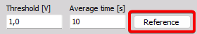
Threshold
The Threshold level determines the trigger level for when the System frequency response measurement will begin. If the measured generator source signal level exceeds the user-defined Threshold level, then the system response measurement will begin. All measurements are performed under the Measure tab section.
Averaging time
The Averaging time determines the used measurement duration for the results. For example, if set to 5 sec then 5 sec duration of data are used and averaged together, starting from the time point that channel level was exceeding the Threshold level.
Ref. frequency
The Reference frequency is the frequency for which the level is used as the basis for when comparing to other frequency levels. The level differences are the values that you will see for the specific microphone channel under the setup screen for that, under the tabs System response [before] and [after].
Source type
The Source type defines the used generator excitation signal type that are send into the microphone cable.
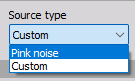
- Pink noise - this should be selected if the attached generator source outputs a pink noise signal. With pink noise all 1/3-octave band levels are equal and therefore there is no Reference settings available for that type.
- Custom - this should be selected if the attached generator source outputs a custom but known signal type. The known signal type must then be defined under the Reference settings button.
For the Custom Source type, the Reference voltage can be set by clicking on the Reference button under the General System frequency response group of parameters:
The Reference voltage values can be set for user-specified frequencies and must be set accordingly to the signal characteristics outputted by the used reference source unit:
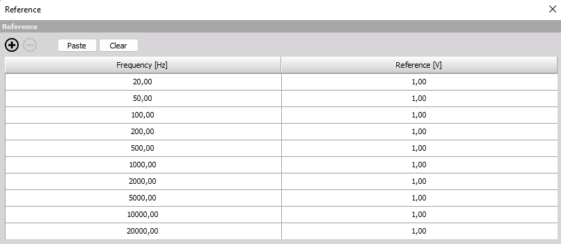
When the reference source unit is turned on and the level is crossing the specified Threshold level then the System response measurement will be activated. While activated 1/3 octave band levels will be averaged over the specified Average time.
NOTE: You need to go to Measure before measurements will be activated.
The System response measurement can be monitored with the System frequency response sub-display found under the pre-defined MC (Microphone Correction) display templates:
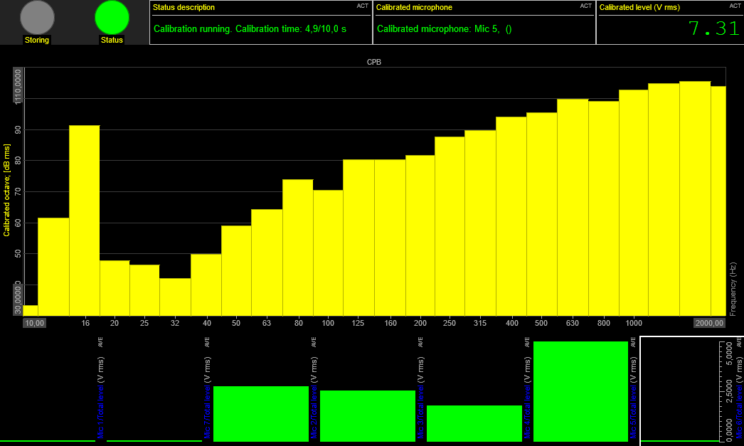
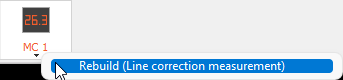
Later on, if the number of microphones used in the test configuration is changed in the setup, then you should update the pre-defined display layout to match the new configuration. This is done by right-clicking and pressing Rebuild on the display layout button relating to the Microphone correction module.
Sensitivity calibration
Sensitivity calibration is used to measure and correct for changes in the microphone sensor sensitivity. Sensitivity calibration is also referred to as Acoustical sensitivity. Similar to the System frequency response - Measurement mode, the Sensitivity calibration can be set to Before or After the actual DUT noise measurements by toggling the Measurement type parameter.

NOTE: Sensitivity calibration will use measured System response data such that sensitivity corrections do not get affected by the system line response, but only relates to the actual microphone.
Measurement type
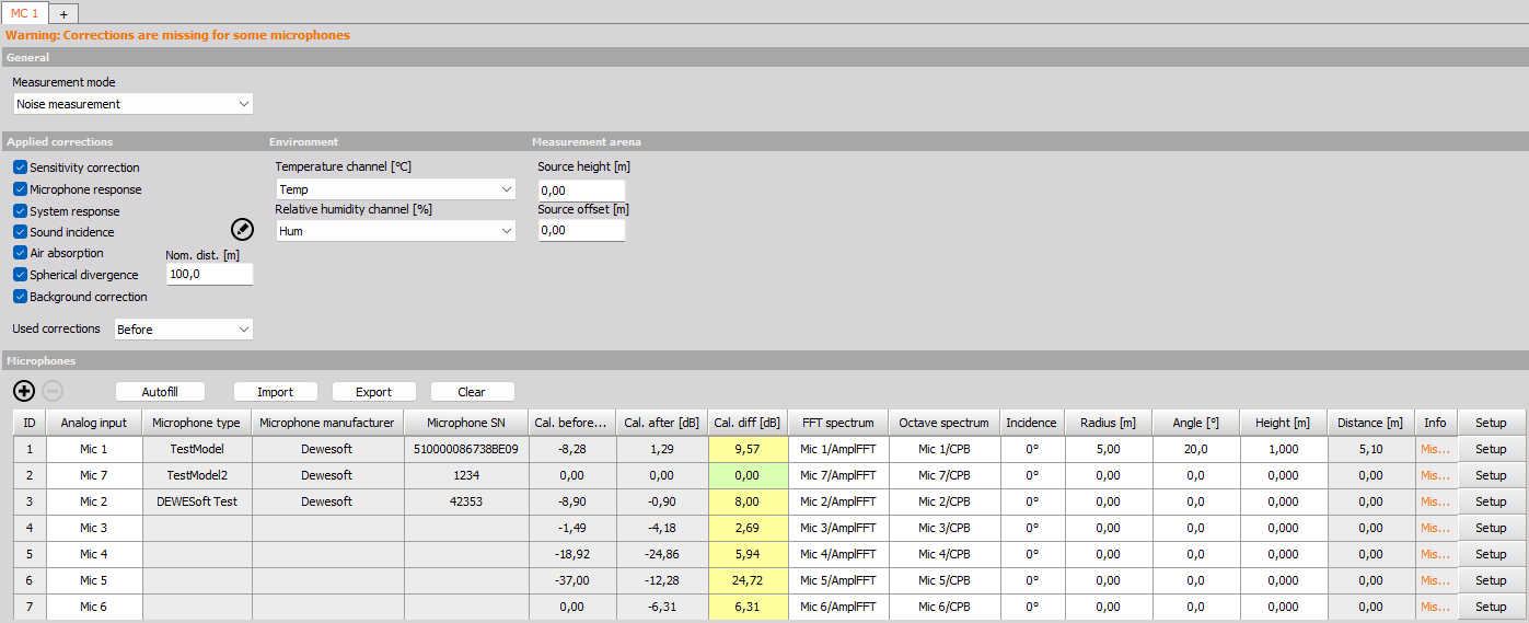
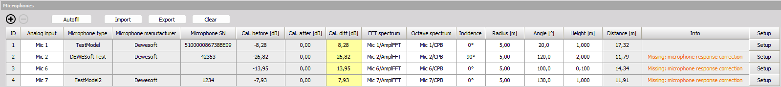
The Measurement type is used similarly for Sensitivity calibration as it is described for the System frequency response mode, but since it is a single value per channel the measured results are shown directly in the Microphones table under the columns Cal. before and Cal. after:

Calibration level
The Sensitivity calibration will start when going to the Measure tab and the Cal. level is detected at one of the microphone inputs. The calibration level should be obtained when a microphone calibrator is mounted on one of the microphones and turned on.
The calibration measurement can be monitored with the Sensitivity calibration sub-display found under the pre-defined MC (Microphone Correction) display templates:
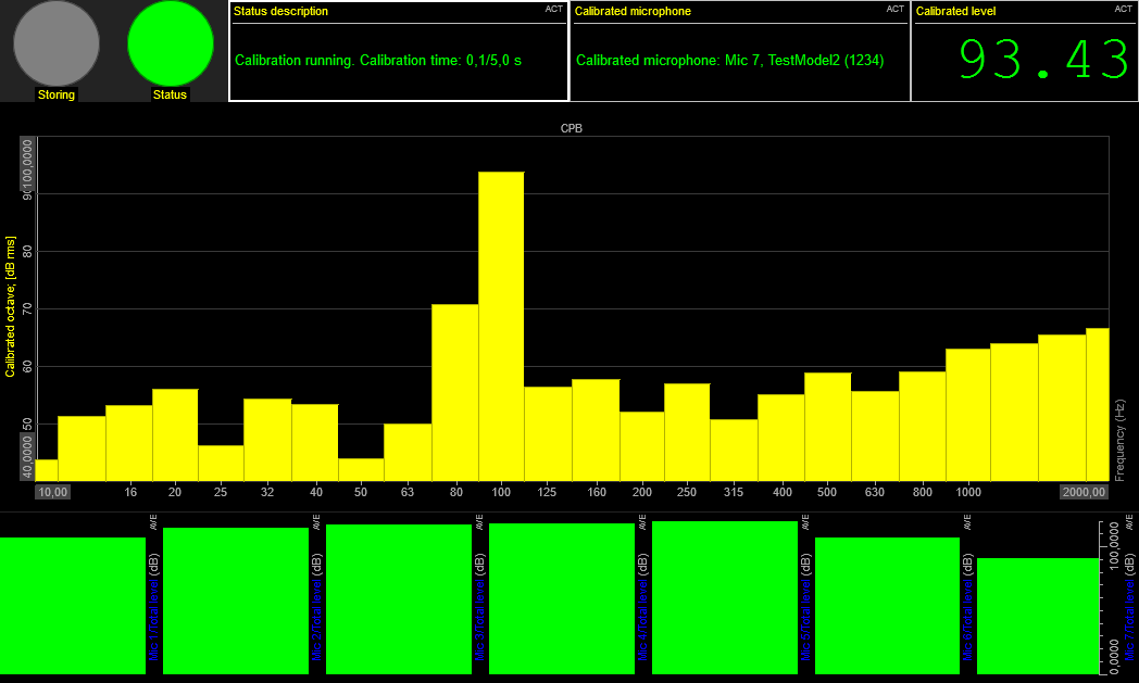
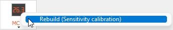
The calibration sub-display title might say System frequency response until you right-click and press Rebuild.
After an active calibrator has been detected the sensitivity calibration will run an averaged measurement over the time duration set by the Average time parameter.
The Status description text field will indicate e.g. if a microphone is being calibrated or if no calibrators have been detected. The Calibrated microphone text field will give information about which microphone that is currently being calibrated.
The octave spectrum in the center and the noise level indicated in the upper right corner will relate to the microphone that is currently being calibrated. The vertical bars level meters at the bottom of the display show the level of all microphone inputs included in the setup.
The Sensitivity calibration results will be visible in the Microphones table under the Cal. before and Cal. after columns. More information can be found under Microphones table - Sensitivity calibration data.
Background noise
Background noise measurements, also referred to as Ambient noise measurements, can be performed before and after the DUT noise measurement.
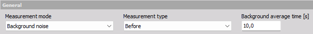
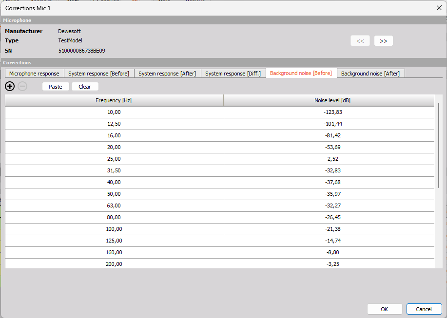
The Measurement type parameter is used similarly for Background noise measurements as it is described for the System frequency response mode. Measured background noise data will be visible under Setup for the individual channels in the Microphones table.
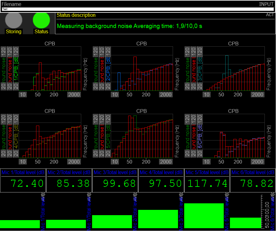
Under the Measure tab a related pre-defined sub-display layout is available for the Background noise Measurement mode.
Noise measurement
The Noise measurement mode must be selected to start the actual DUT noise measurements that will have the system- and microphone corrections applied to it, together with a list of other optional corrections. All corrections that should be taken into account can be selected under the Applied corrections section.
Noise measurement should be selected after the required workflow of Before-measurements have been performed, by using the other Measurement modes.
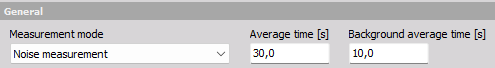
For the DUT Noise measurement mode you can set the averaging time for the actual noise measurement.
The DUT noise measurement, can be managed via the related Measure sub-display.
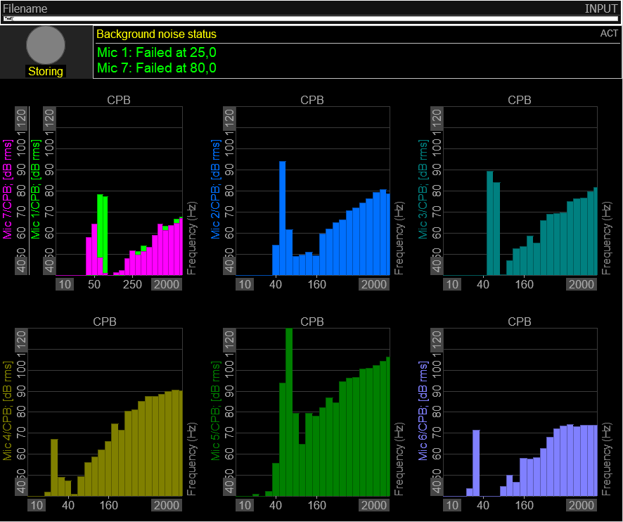
At the Measure tab the pre-defined Noise measurements sub-display (under MC 1) should be used to perform the DUT noise measurements.
The display layout shows 2D graph widgets plotting 1/3-octave band spectra for all included microphones, and a status read-out indicating if the measured levels are too close to the pre-measured background noise levels.
The channel ‘Background noise status’ is shown with a Digital meter display widget, where the 1/3 octave bands are shown for those where the background noise levels are exceeding the tolerance level set under the module’s extension settings:
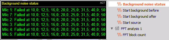
Please see the section Extension settings for more information.
Both the Background noise before and -after, and the ‘DUT’ Source noise are 1/3-octave band spectra which can be overlayed in a 2D graph display widget in order to overview and compare the DUT noise with the background noise.
Applied corrections
When the Measurement mode ‘Noise measurement’ is selected under Ch. setup a list of different corrections can be checked On or Off, to be applied to the DUT noise measurements.
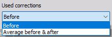
A subset of the available corrections has correction data from both before and after the DUT noise measurements. You can choose between using the correction data from Before the DUT measurements or Averaged correction data between before and after the DUT measurements:
Sensitivity correction
The sensitivity correction will apply a microphone calibration correction using the measured calibration data from the Sensitivity calibration Measurement mode.
Microphone response
The microphone response correction will deal with influences of the microphone itself. Open circuit microphone response data can be added manually or copy/paste into the related table found under setup for the individual microphones:
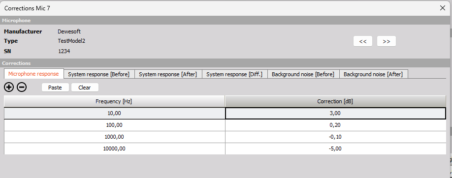
The open circuit microphone response data is typically provided with the microphones from the manufacturer.
System response
By enabling the correction for the System response, all influences measured from the System frequency response correction measurements will be taken into account.
The System response results can be found for the individual microphones under the setup buttons in the Microphones table.
Sound incidence
Microphones will typically have a free-field response curve that varies with incidence angle of the received noise. By enabling this correction the DUT noise measurements will be corrected for the different microphone incidence angles used.
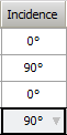
The individual microphone incidence angles can be set in the Microphones table under the column ‘Incidence’.
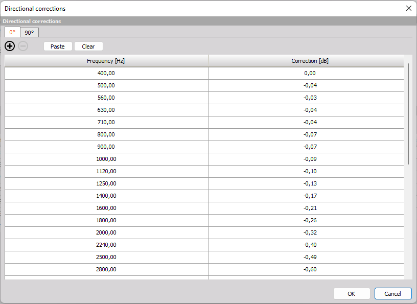
The different incidence angle-dependent response curves can be edited by entering the Directional corrections setup, by pressing the pencil button shown below:

The Directional corrections setup contains a tab for each Incidence angle available to choose for the individual microphones in the Microphones table.
Air absorption
The air in the atmosphere will absorb some of the noise energy. How much energy that will be absorbed depends on the temperature and humidity of the air together with the distance between the DUT noise source and a specific microphone position.
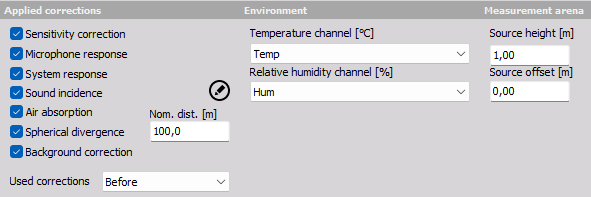
Additional input parameters are available under the Environment and Measurement area sections which are used to determine such air absorption data for the microphone locations:
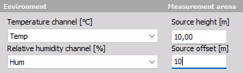
For the temperature and humidity parameters you must select an input channel. The temperature channel must have the unit degrees celsius [ºC] and the humidity channel must have the unit percent [%].
The effect of the change in atmospheric sound absorption is defined by: $$\delta =0.01\cdot[\alpha(i) - \alpha(i)_0]\cdot D ,$$ where $\alpha(i)$ is the absorption coefficient for the test conditions, $\alpha(i)_0$ is the absorption coefficient for the reference conditions, $D$ is the distance, and $i$ is one-third octave band index.
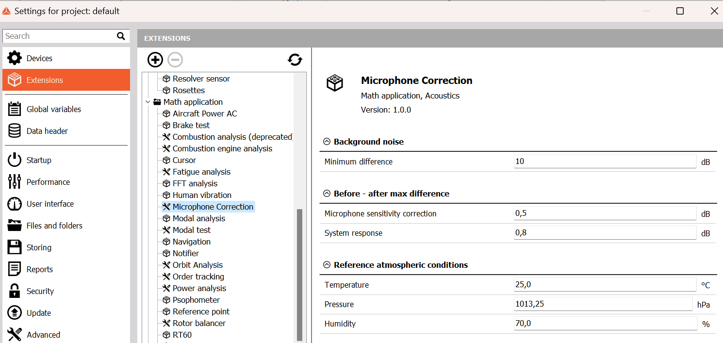
The reference conditions are by default set to use a temperature of 25 °C, and a humidity of 70 %, but these can be changed under project settings for the Microphone correction module, as indicated below:
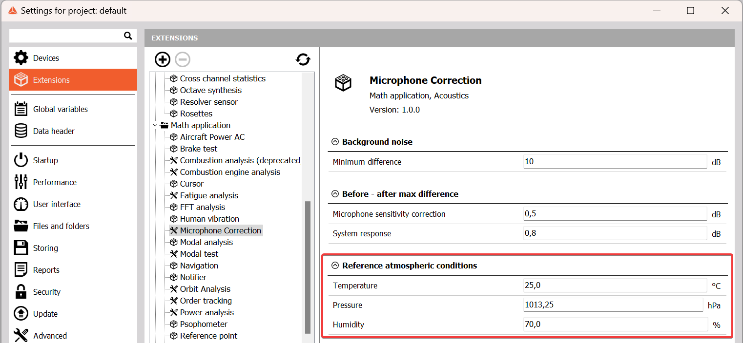
How to enter the Microphone correction project settings are described in the Module extension settings section.
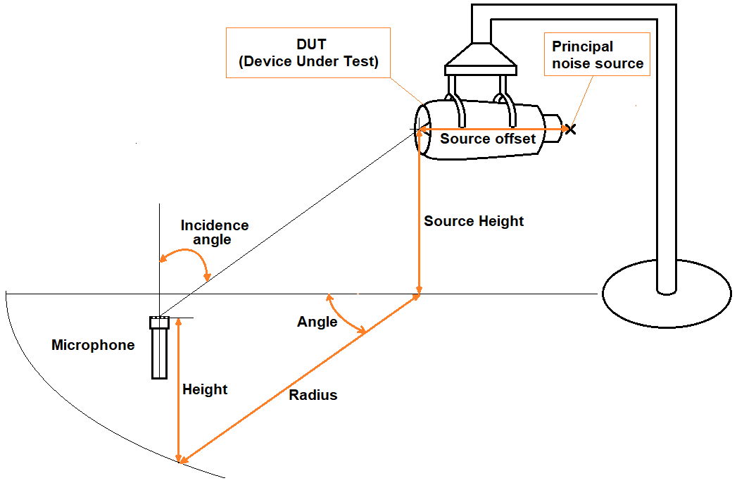
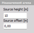
To determine the distances between the DUT and the individual microphones both the DUT source position and the microphone positions are used. The DUT source position is determined with the Measurement area parameters:
The Source offset relates to the distance between the DUT physical center and the actual/principal DUT noise source. This is illustrated in the setup drawing in the beginning of this article.
The microphone positions are managed in the Microphones table where the Distance column shows the determined distances between the microphones and the DUT principal noise source.
Spherical divergence
The Spherical divergence correction will adjust the sound pressure to relate to a nominal distance from the DUT.
By assuming an attenuation rate given by
$$ \frac{\text{1}}{\text{distance}^2}, $$
distances different from the nominal distance will be corrected accordingly.
For example if the nominal distance was set to 1 m and the actual distance was 2 m then the adjustment would be +6 dB.
The nominal distance for the spherical divergence can be set using the Nom. dist. parameter.
Microphones table
The Microphones table contains all microphone correction settings that relate to individual microphones.
Additionally, correction data for a given microphone channel are available by clicking the related Setup button in the microphone table row.
Adding microphones
First, microphones must be added to the Microphones table. This can be done either manually by clicking on the $+$ button and selecting a microphone under the Analog input table column, or it can be done automatically by clicking the Autofill button.
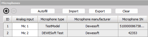
Autofill
The Autofill button will add a row in the table for each Used Analog input that has Sound pressure as its Physical quantity.
Using Autofill will add the Microphone Type, Manufacturer, and Serial number, found from the Analog input Setup to the table rows as shown in the picture above. More information about setting up the Analog inputs can be found here: Analog input Setup.
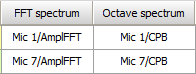
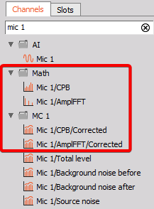
If FFT and Octave analyzers are processing the microphone channel data then those output spectra will also be added to the spectrum related table columns:
Import / Export correction data
The Import and Export buttons located over the Microphones table next to Autofill button, can be used to export or import microphone correction data to or from the table.
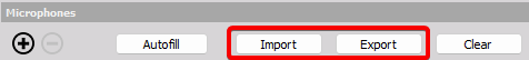
Clicking on the Export button will open settings for what to export and to what Directory:
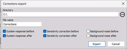
Each microphone channel (table row) will be exported to a separate TXT file. Each channel TXT file will include information about the Microphone Type and Serial number, together with the data that has been selected to be exported via the check boxes.
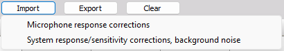
Clicking on the Import button let you import microphone response data or system response data together with sensitivity correction data and background noise data:
Sensitivity calibration data
The table columns Cal. before and Cal. after are showing the measured Sensitivity calibration results. See more about how to obtain such calibration sensitivity results under the section Measurement mode - Sensitivity calibration.
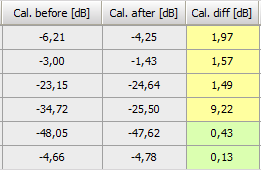
The column Cal. diff shows the Cal. after value minus the Cal. before value, and will have a:
- yellow - background color if the ‘Before - after max difference’ for Microphone sensitivity correction is exceeded
- green - background color if the max difference is not exceeded.
The parameter ‘Before - after max difference’ for Microphone sensitivity corrections can be changed under the module’s Extension settings.
Spectral data
The columns FFT spectrum and Octave spectrum will use all enabled Applied corrections:
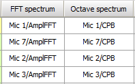
FFT and Octave analysis math modules must be set up to process the microphone channels before such related spectra can be selected in the columns:
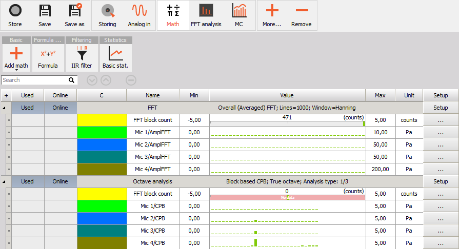
The picture above shows the Math setup tab with an FFT analyzer module and an Octave analyzer module having a set of microphone channels added for processing. The output spectral channels from these analysis modules can be added for applying corrections in the Microphones table for the FFT spectrum and Octave spectrum columns.
Hereafter, on the Measure tab you will be able to select and compare spectral data with and without corrections applied:
Incidence angle
The Incidence angle of each microphone can be set to one of the pre-defined angles specified under the Applied corrections - Sound incidence settings. The incidence angle should be relative to the direction line between the microphone and the principal DUT noise source location:
Location and distance to DUT
The location of the microphones are defined with cylindrical coordinates where the DUT noise source is at the circle center. Based on the Radius, Angle, and Height, the location of the microphones are specified by the user.
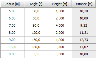
The Distance column in the table is determined from the specified microphone location parameters together with the parameters defining the DUT principal noise location, specified under Measurement area:
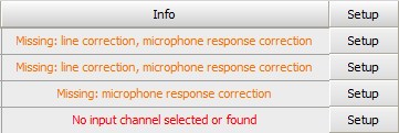
Information and setup
The microphone table Info column will indicate missing input data required to perform the corrections on DUT noise measurements. Some examples of possible information messages are shown below:
The Setup button for each microphone will open the settings for the microphone Response data and the System response data. These settings are described under the Applied corrections - Microphone response and under Measurement modes - System response.
Module extension settings
The Microphone correction module’s Extensions settings will appear when clicking on the extension settings icon, as shown below. The extension settings icon is found in the top right corner of the module setup:

Alternatively you can click on Options in the top right corner and select Settings, then go to the Extensions tab section and find the Microphone Correction module under Math applications in the list of active modules.
The Extension settings for the module let the user change the level tolerances for the different measurement modes.
Background noise tolerance
The Background noise - Minimum difference level is used for the background noise status channel as shown in the section for measurement modes - Noise measurement.
If the DUT Noise measurements and the background noise measurements have 1/3 octave band level differences lower than the set dB level then those bands will be indicated by the Background noise status channel.
Before - after max difference tolerances
Under ‘Before - after max difference’ you can set tolerance levels used for the two Measurements modes - Sensitivity calibration and System response:
Microphone sensitivity correction - tolerance will be used to determine the background color in the Microphones table - Sensitivity calibration data.
System response difference - tolerance will be used to determine the background color for both the Microphone response data and the System response data.