TEDS Sensors
TEDS stands for Transducer Electronic DataSheet. It is an EEPROM device embedded in a sensor or a sensor’s connector that contains information such as serial number, calibration dates, and other calibration factors. TEDS allows sensors to act in a truly “plug and play” fashion, eliminating some or all manual entry during setup and ensuring that the correct settings are applied.
Aditional links:
A lot of manufacturers offer a TEDS enabled sensor. In that case, we can simply connect the sensor. When the sensor is read, we can see the serial number, amplifier settings, and sensor sensitivity. In Edit sensor, we can see the additional information like manufacturer, sensor type.
Since this is an off-the-shelf sensor, DewesoftX doesn’t let us write anything to the sensor. If we have to change something on standard sensors, we have to use the Dewesoft TEDS Editor. Using this tool, we can perform calibration of standard sensors.
NOTE: If the sensor is in IEPE mode, we must choose IEPE mode before DewesoftX searches for the TEDS sensor.
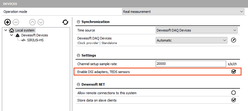
TEDS detection has to be enabled to read TEDS sensors. Activate the checkbox Enable DSI adapters, TEDS sensors in DewesoftX Settings.
How to connect the TEDS chip?
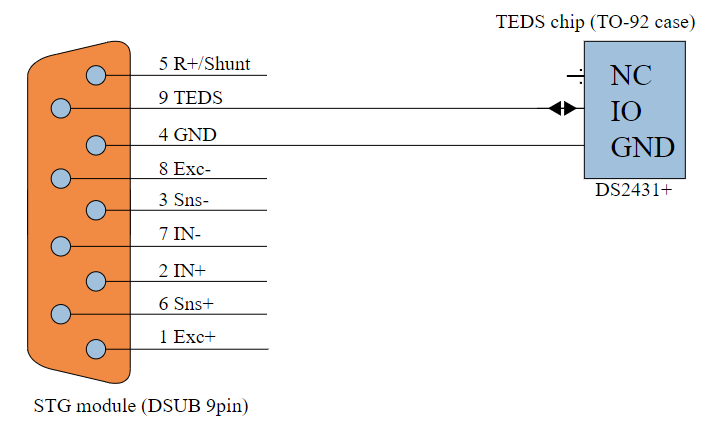
If our sensor doesn’t not have a TEDS chip built-in, we can easily create one. First, we need to modify our sensor and add a TEDS chip. This is usually done on the connector. In this example, we use the DS24B33 chip from Maxim, which is large enough to store all amplifier settings. In the illustration below, we can see the connection for a SIRIUS STG module (with a 9-pin DSUB).
WARNING: Wrong polarity can destroy a TEDS chip! With the TO-92 chip casing, it is easy to turn the chip around, so be careful.
Working with TEDS in DewesoftX
When an empty TEDS chip is connected, nothing will pop up. However, you can check if the TEDS chip is working by entering Channel Setup. The button Write to TEDS and an additional TEDS tab will be visible.
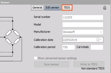
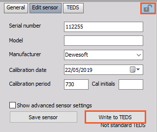
To edit the TEDS, open the Edit sensor tab in channel setup where the TEDS sensor is connected. Click on the lock icon in the top right corner to enable editing. You can enter the sensor data (Serial number, Model, Manufacturer, Calibration data) and press the Write to TEDS button to save it to the TEDS chip.
NOTE: DewesoftX doesn’t allow writing to TEDS if it was created by a manufacturer other than Dewesoft, in which case we can use TEDS editor.
The major advantage of Dewesoft TEDS is that, apart from the sensor, all amplifier settings (like range, type of input, filter, EXC voltage…) are also stored. Multiple templates can be written to a chip if one does not suffice. Additional information can be saved, including passwords to prevent other users from rewriting the sensor. If the option Show advanced sensor settings is checked, the user can enter Advanced write options after clicking on the Save sensor button.
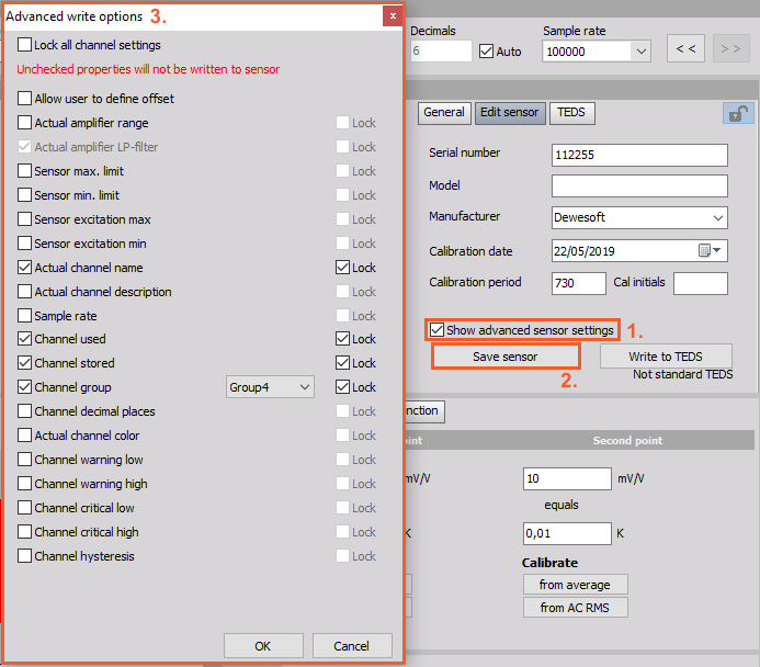
On top of Advanced write options, Lock all channel settings option can be disabled in order to change previously locked settings. There are several options you can choose from, some described below:
Allow user to define offset - a TEDS sensor normally defines the fixed scale and offset, but if this is checked, the user can additionally set sensor offset (e.g. for zeroing)
Write channel name to the sensor - write the channel name to sensor stored in SensorDataBase and retrieve it when connected to a different physical channel (this is not written to TEDS)
Sensor max./min. limit - defines the absolute maximum and minimum (physical) value that the sensor can output. If it is set to INF, it will calculate it automatically from range and scaling. This will set the Min and Max values of the channel.
Sensor excitation max/min - defines the limit of excitation that the sensor can work from
Password for TEDS - password protection.
When the TEDS sensor with password protection is connected to other channels, it will be read automatically, but when unlocking the sensor, the user will need to enter the password.
Dewesoft TEDS Editor
DeweTEDSEditor is a tool managing TEDS chips. It is completely free of charge. You do not need a Dewesoft instrument to use DeweTEDSEditor as it works with other readers, such as OneWire. You can find the DeweTEDSEditor on our web page in the Download - Other software section.
Before reading from the device, select the right channel number to which you have connected TEDS. After reading from the device, the information from the sensor will appear on screen.
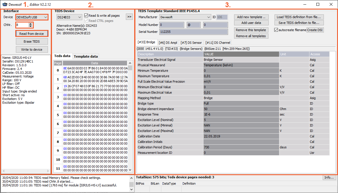
The screen is divided into three sections:
- Interface
- TEDS device
- TEDS template
1. Interface
The left side is the Interface section and shows us the three Interfaces that Dewesoft allows to have - Dewesoft USB device, Amplifiers RS232, and OneWire reader. If we choose for example Dewesoft device in the Interface section, we also need to choose the right Channel number (ChNr.). To read the sensor data click on Read from the device. Below, we receive all the information of the amplifier or the interface: its name, serial number, calibration date, excitation, and more.
With a click on Erase TEDS, you delete all the data from the chip. Button Write to device uploads all the templates to the chip memory you have defined in the third section.
2. TEDS device
TEDS device section shows us what device was found after we have pressed Read from the device. Below is the chip name (Alternative), size of the memory, and its serial number.
NOTE: Every TEDS chip has a unique serial number.
At the bottom is the chip data in binary format.
3. TEDS template
At the top left part of the section, there is additional information about the sensor. We can see manufacturer, ID, model number, and serial number. Right of information there are buttons for working with templates. You can add, delete, export, or import templates.
In the bottom part of the section, there are templates that are written to the chip. You can scroll through them by clicking on their tabs.
NOTE: Calibration date and other information of TEDS can be only changed if it was created by Dewesoft or if somebody else made it with the Dewesoft tool (TEDS editor).
Under all three sections, there is an event shower. All events since the opening of the TEDS editor are listed there.
IMPORTANT: While using the TEDS editor, you really need to know what you are doing!.
Creating a New TEDS Sensor
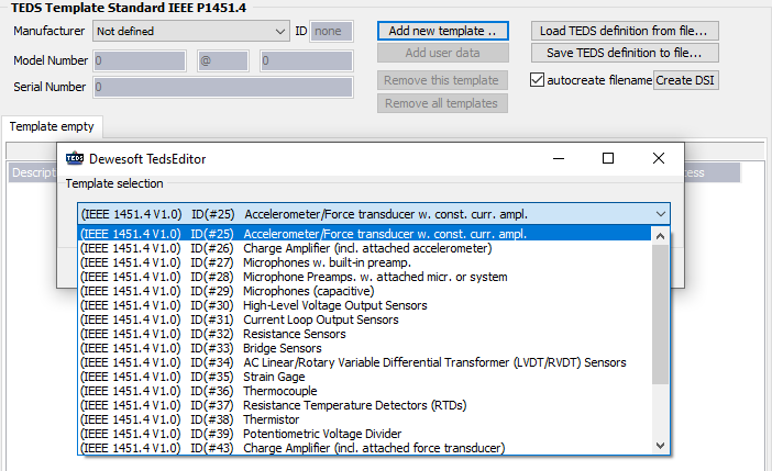
To create a new TEDS sensor from scratch you need to connect it first. When connected, click on Read from device and a sensor without data will appear. First of all, you need to define the manufacturer, model number, and serial number. If field definition does match with your data, leave them empty and you can define them later.
Adding a new template is done by clicking Add new template button. All standard IEEE sensors are supported and any field can be later added to the template in the user editor. Additional templates can be added to the first one. One of the options are a standard calibration table, calibration curve, or frequency response curve. Also, the Dewesoft amplifier template to define all amplifier properties can be added (Input type, Range, LP, and HP filter, …).
Some of channel template properties:
- LP filter - defines which low pass filter will be chosen for the amplifier (the advanced option has also type and filter order),
- User coupling - defines which high pass filter will be used (either sensor is AC or DC coupled),
- Measurement - defines which measurement type amplifier is set to (voltage, bridge, potentiometer),
- User excitation - defines the nominal excitation voltage the amplifier is set to by default,
- Input type - defines either amplifier is set to a differential or single-ended mode,
- User range - defines the range that the amplifier must be set to,
- Range dual-core - defines if high-dynamic dual-core ADC technology is used (related only to Dewesoft amplifiers).
We can also add Dewesoft sensor properties by adding the option to have a longer sensor description, serial number, limits, polarity, and so on. Below are some sensor template properties:
- User manufacturer - this field overrides the manufacturer ID set in the standard template
- User model name - this field overrides the default model name (user can use alphanumeric characters of any length)
- User serial number - this field overrides the default serial number (user can use alphanumeric characters of any length)
- Physical measurand - defines which physical quantity sensor is measuring (according to SI unit system)
- User scale - defines the sensor scale according to Dewesoft standard (so SI unit conversion can be used) - unit of measurement must comply with Dewesoft SI unit scheme
- User Sensor Limits - defines the absolute minimum and maximum that the sensor can measure (will be used for display purposes)
- Additional bridge props - the properties for strain gage sensors not defined by the IEEE standard
- Sensor polarity - defines standard sensor polarity
- User Sensor offset changeable - if yes, the user can change the offset at a later time (when setting up the initial load, for example)
- User Sensor scale changeable - if yes, the user can assign an additional scale factor at a later time
- Calibration info - additional info from calibration
Once everything is defined, the data can be written to the chip using the Write to device button or save sensor configuration for future use by using the Save TEDS definition to file.
Dewesoft TEDS Library (TDL)
In the Dewesoft TEDS library, there is a description of how templates in the TEDS editor work. With the use of this file, people can learn how to read all the information written in Dewesoft’s templates. You can read all the data till the last bit, but no more than that. You can download the file from our web page.
What Parameters Can Be Stored in a TEDS Chip?
The TEDS standard defines multiple sections of information that can be stored on the chip. In addition, it defines numerous templates that are used for various types of sensors, and for containing calibration information.
The four basic types of TEDS information are:
- Basic TEDS (64 bits)
- Standard Templates (25 to 39, and 43 bits)
- Calibration Templates(40-42 bits)
- User TEDS
Let’s look at each one of these four types:
| Sensor Template ID | Bit Length | Allowable Range |
|---|---|---|
| Manufacturer ID | 14 | 17 to 16,381 |
| Model | 15 | 0 to 32,767 |
| Version Letter | 5 | A-Z |
| Version Number | 6 | 0 to 63 |
| Serial | 24 | 0 - 16,777,215 |
Following this basic TEDS information is an ID reference to the appropriate standard sensor template, numbered from 25 to 39 (plus 43):
| Sensor Template ID | Type of Sensor / Transducer |
|---|---|
| 25 | Acceleration & Force Sensors (IEPE) |
| 26 | Charge amp with an accelerometer |
| 27 | Microphone with integrated preamp (usually IEPE) |
| 28 | Microphone preamp (can also specify an attached microphone) |
| 29 | Microphones (capacitive) |
| 30 | High-level voltage output sensors (of all kinds) |
| 31 | Current loop (4-20 mA or 0-20 mA) sensors (of all kinds) |
| 32 | Resistance-based sensors (for potentiometric sensors use #39) |
| 33 | Bridge sensors (load, pressure, accel bridge linear output sensors) |
| 34 | AC Linear/Rotary Variable Differential Transformer (LVDT/RVDT) Sensors |
| 35 | Strain gage sensors (linear or not, gage factor, etc.) |
| 36 | Thermocouples (all standard types are supported) |
| 37 | Resistance Temperature Detector sensors (RTDs) |
| 38 | Thermistors (using the Steinhart-Hart equation) |
| 39 | Potentiometric sensors (resistive voltage dividers) |
| 43 | Charge Amplifier (with an attached force transducer) |
You may be wondering what these sensor templates look like, so let’s look at one of the smaller ones:
| Property | Description | Access | Bits | DataType and Range | Units |
|---|---|---|---|---|---|
| TEMPLATE | Template ID | 8 | Integer (value = 36) | - | |
| %ElecSigType | Electrical signal type | ID | - | Assign=0, “Voltage Sensor | - |
| %MinPhysVal | Minimum Temperature | CAL | 11 | ConRes (-273 to 1,770, step 1) | °C |
| %MaxPhysVal | Maximum Temperature | CAL | 11 | ConRes (-273 to 1,770, step 1) | °C |
| %MinElecVal | Minimum Electrical Output | CAL | 7 | ConRes (-25E-3 to 0.1 step 1E-3) | V |
| %MaxElecVal | Maximum Electrical Output | CAL | 7 | ConRes (-25E-3 to 0.1 step 1E-3) | V |
| %MapMeth | Mapping Method | ID | - | Assign=3, “Thermocouple | - |
| %TCType | Thermocouple Type | ID | 4 | B, E, J, K, N, R, S, T, or non-std | - |
| %CJSource | Cold Junction Compensation Required | ID | 1 | CJC required or compensated | - |
| %SensorImped | Thermocouple resistance | ID | 12 | ConRelRes (1 to 319k, ±0.155%) | Ohms |
| %RespTime | Response Time | ID | 6 | ConRelRes (1E-6 to 7.9, ±15%) | seconds |
| %CalDate | Calibration Date | CAL | 16 | DATE | - |
| %CalInitials | Calibration Initials | CAL | 15 | CHRS | - |
| %CalPeriod | Calibration Period | CAL | 12 | UNINT | days |
| %MeasID | Measurement Location ID | USR | 11 | UNINT | - |
Then we have an ID reference to one of three standard calibration templates, numbered from 40 to 42.
| Sensor Template ID | Calibration Template Name | Calibration Type |
|---|---|---|
| 40 | Calibration Table | Multiple data pairs define the output scaling of the sensor |
| 41 | Calibration Curve | A multi-segment, multi-polynomial calibration curve defines the output scaling of the sensor |
| 42 | Frequency Response Table | A set of amplitude-frequency data pairs defines the frequency response function of the sensor |
Then finally there is a user area, where additional information can be added by the user or the DAQ system. Dewesoft takes full advantage of these and also in its own TEDS-connected sensor database, as we will explain below.