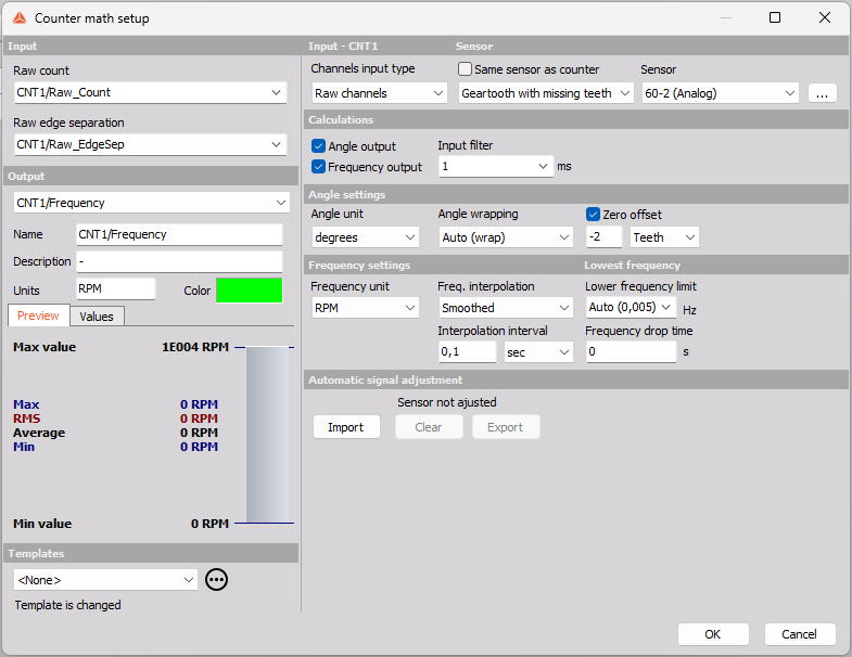
Counter math
With the Counter math module it is possible to determine and recalculate counter angle- and frequency outputs while measuring, online, and during datafile analysis after a measurement, offline.
The Counter math module settings and the software part of the basic Counter module is the same and both are covered on this page.
For hardware settings on counter channels please see the Counters page.
For configuring Counter sensor definitions please see the Counter Sensors page.
This can be useful when you e.g. want to fix a faulty counter setting that wasn’t caught during the measurement, or if you want to tune a setting or two to see if that produces better results.
NOTE: Remember to store the “Raw edge separation” and “Raw count” channels during the measurements, since such data is required to perform the recalculation.
Counter math supports features like frequency smoothing, teeth size adjustment, software filters, and angle wrapping, all described in sections below.
If the results from Counter math turn out to be better for your specific datafile, you can also use the math output as input to other modules that work with counters, such as Order Tracking or Torsional Vibration.
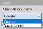
Input Channels
The Counter math module supports both counter channels and raw channels as inputs to process the angle and frequency outputs.
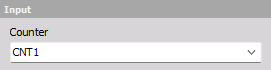
Counter
If you select Counter as Input type, then you must select a Counter channel as input on the left side of the setup page:
Raw Channels
If you select Raw channels then you have to select two channels as input. One for the raw pulse count and one for the raw edge separation:
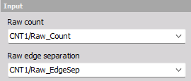
Together the raw count channel and the raw edge separation channel can be used like a Counter input to recalculate the angle and frequency outputs with Super Counter precision.
Sensor
By default the expected sensor type is set equal to the sensor type used in the related Counter channel module, for the Input channel.
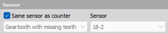
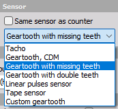
Sensor Type
The sensor type can be changed manually by un-checking the “Same sensor as counter” checkbox:
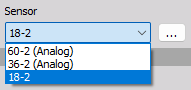
In that case the Sensor configuration must also be selected or defined under the three dots […]:
Calculations
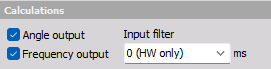
Select which results you want. You can check on Angle (phase) data, Frequency (speed) data or both.
Input Filter
On top of the used Counter hardware Input filter you can enable a Counter math software Input filter.
The SW filter can be used to prevent unexpected double counts. It works like a Hold-off function, where subsequent pulse will be ignored up until the set Input filter length.
The filter should be set to react a bit faster than the expected event/pulse rate, and at the same time it should be set a bit slower than the time interval where signal glitches are expected.
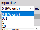
If set to 0 then only the Counter HW filter will be used.
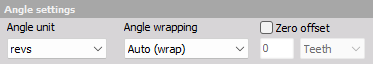
Angle Settings
Parameters related to the Angle output channel.
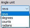
Angle Unit
The output angle data can be set to have one of the following units:
- Revs - revolutions and fractions of revolutions
- degrees - 0º - 360º if wrapped
- Counts - number of pulses and fraction of pulses.
- Radians - 0 - 2π, if wrapped.
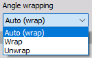
Angle Wrapping
The angle data can be set to Wrap back and start from 0 again when a full rotation has appeared. By selecting Unwrap the angle data will continue to accumulate angles over multiple rotations.
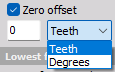
Zero (Angle) Offset
The Zero angle offset can be shifted either by a number of gear teeth or by a specific angle defined in degrees:
Frequency Settings
Parameters related to the Frequency output channel.
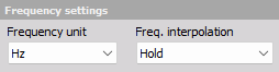
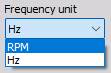
Frequency Unit
The output frequency data can be set to have one of the following units:
- RPM - Rounds Per Minute
- Hz - Rounds per second
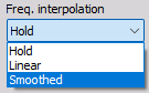
Frequency Interpolation
The frequency or speed data values calculated in-between pulses (between raw-count steps) can be handled in multiple ways. The following interpolation types are supported:
- Hold - No interpolation. Instead the speed value is kept until the next raw count step occurs.
- Linear - Linear interpolation between raw count steps.
- Smoothed - Moving averaged speeds with a user-defined averaging time or number of revolutions.
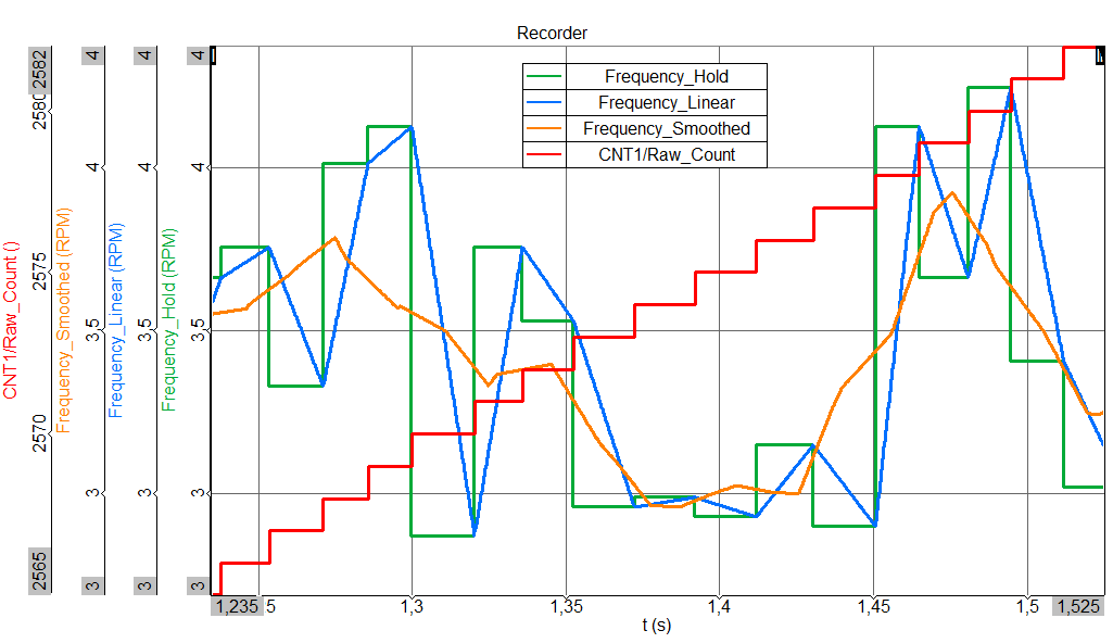
In the Picture above the three interpolation types are compared together with the related raw count data.
Interpolation Interval (Smoothed)
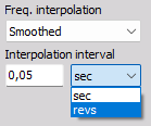
When Freq. interpolation is set to Smoothed, then the smoothing strength can be adjusted. The Smoothing interpolation is a linear moving average where the moving average interval is the user-defined Interpolation interval.
The Interpolation interval can have either a fixed time length set in seconds, or a fixed angle length set in number of revolutions.
Lowest Frequency
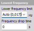
Lowest Frequency Limit
If the measured frequency or speed drops below the set Lower frequency limit, then it is assumed to be 0.
The lowest frequency possible to calculate depends on the sensor and the allowed calculation delay, in such a way that at least one pulse is found in the range of the ”allowed” time.
For example, if we are working with a gear tooth with missing teeth, the biggest gap is an important factor for this.
The allowed calculation delay is determined by:
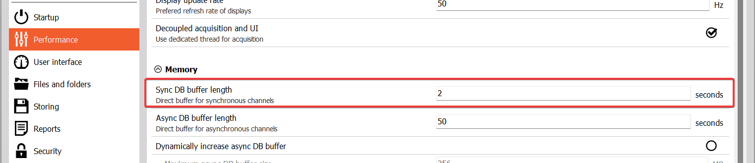
Taking the Maximum calculation delay from either the project settings parameter or 2 seconds (so whatever is the longest of those two numbers).
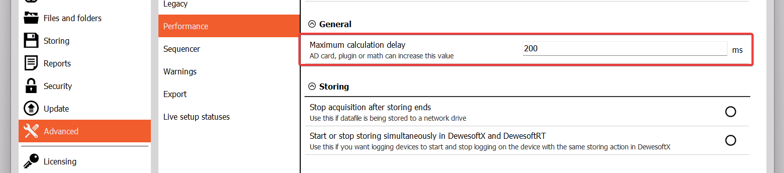
Afterwards this calculation delay is then limited to one half of the Sync DB buffer length project settings parameter (so whatever is the shortest of those two numbers).
$$f_{min} = \frac{1}{\text{Gap}_{max} \cdot \text{min}(\text{max}(2 s, \text{Calc. delay}), \frac{\text{Sync buffer}}{2})},$$
where $\text{Gap}_{max}$ is the biggest gap in number of pulses relative to the number of pulses per revolution:
$$\text{Gap}_{max} = \frac{\text{pulses per rev}}{\text{max. pulse gap}}$$
Example 1 - Tacho
- An analog tacho signal with one pulse per revolution
- Maximum calculation delay of 200 ms
- Sync DB buffer length of 2 seconds
$$f_{min} = \frac{1}{1 \cdot \text{min}(\text{max}(2 s, 0.200 s), \frac{2 s}{2})} = 1 Hz$$
Example 2 - Encoder
- An encoder with 360 pulses per revolution
- Maximum calculation delay of 200 ms
- Sync DB buffer length of 4 seconds
$$f_{min} = \frac{1}{360 \cdot \text{min}(\text{max}(2 s, 0.200 s), \frac{4 s}{2})} = \frac{1}{360 \cdot 2} = 0,00139 Hz$$
Example 3 - Gear with missing tooth
- A gear with 60 teeth but one missing so actually 59 teeth (referred to as “60-1”)
- we assume the missing tooth creates a max gap equal to 3 teeth.
- Maximum calculation delay of 200 ms
- Sync DB buffer length of 2 seconds
$$f_{min} = \frac{3}{60 \cdot \text{min}(\text{max}(2 s, 0.200 s), \frac{2 s}{2})} = \frac{3}{60} = 0,05 Hz$$
Frequency Drop Time
If the speed drops below the Lower frequency limit, then the Counter math frequency output will use an artificial ramp down towards 0 over the specified Frequency drop time.
Exceptions are:
- If the counter speed suddenly drops below the Lower frequency limit in an “un-natural” way
- If no pulse is detected in the ”allowed” region of the calculation delay.
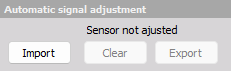
Automatic Signal Adjustment
Automatic signal adjustment can be used to detect and use precise distances between individual gear teeth and hereby improve the angle and frequency results:
Automatic signal adjustment works for all the sensors that have a reference, with which they can determine the position during roation (geartooth with missing teeth, encoder with zero pulse, tape sensor, ..). If the sensor does not have a zero pulse (geartooth) we cannot determine the position of the teeth that needs the correction.