CMP capture module — User manual
Contents
- Purpose and prerequisites
- Add and navigate the module
- Select the network interface
- Set capture module properties
- Configure interfaces and streams manually
- Scan for signals
- Check and use the configuration
- Troubleshooting
- References and verification
1. Purpose and prerequisites
The capture module encodes local openDAQ signals into ASAM CMP packets and sends them through a selected Ethernet adapter. A CMP data sink receives and decodes those packets. The upstream implementation requires Npcap on Windows with WinPcap API-compatible Mode enabled. Source: openDAQ ASAM CMP Modules
The configuration hierarchy is:
CMP capture module
  Network interface and device properties
  Interface: ID, name, signal type
    Stream: ID, name, source signal
    Additional streams...
  Additional interfaces...
Before configuring it, make the Dewesofts OpenDaq compatible device (in this case IOLITE-X) available in DewesoftX and configure the source channels you want to forward. Have the receiving system’s expected device, interface and stream identifiers available.
Scope: this is the device-side sender workflow. Dewesoft’s separate CMP data sink plugin has a different setup procedure; its Scan for interfaces command is different from Scan for signals shown here. Source: Dewesoft CMP receiving-plugin guide
2. Add and navigate the module
- Open Measure → Config.
- Select IOLITE-X in device configuration mode.
- Click More… in the device toolbar.
- Under Aerospace and automotive, click CMP capture module.
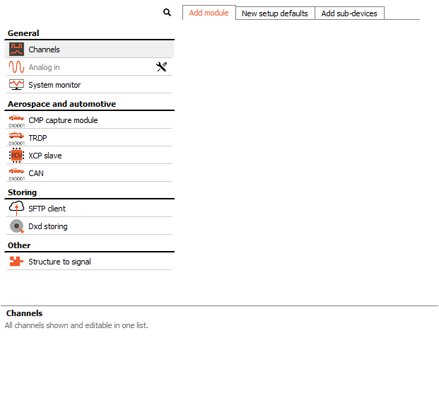 Figure 1. The module is added from the selected IOLITE-X device’s More… menu.
The module opens with a tab such as AsamCmpCaptureModule_1. Its configuration contains Network, Properties, and Interfaces sections.
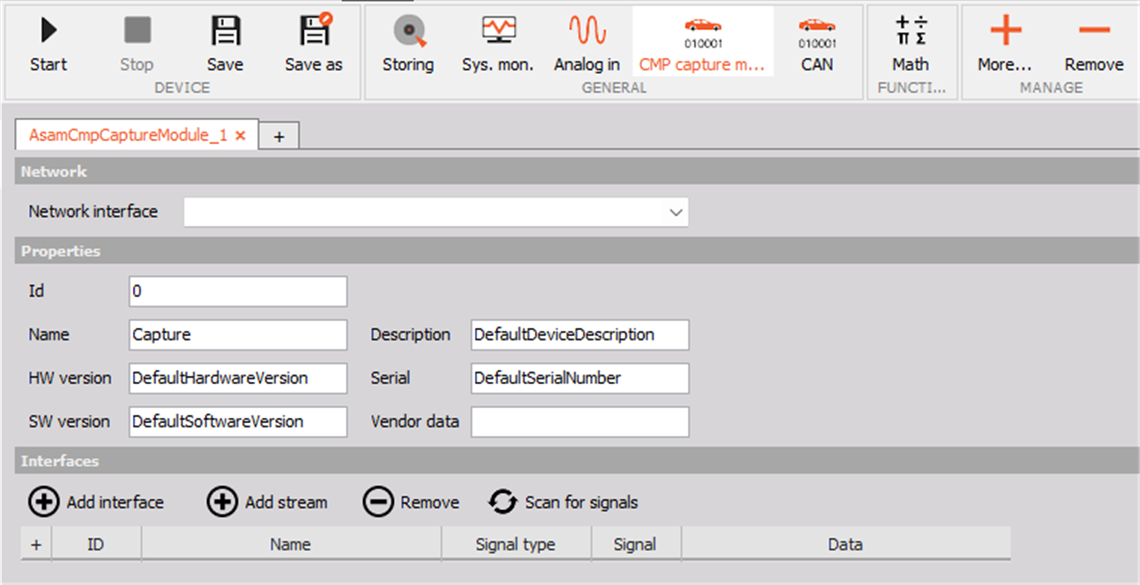
Figure 2. Initial configuration. The empty adapter and interface list are the initial state of the example.
The + beside the module tab creates another capture module instance. Each instance has its own tab. The Used / Unused selector is at the far right of the module’s tab bar.
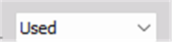
Figure 3. Keep the required instance set to Used.
3. Select the network interface
In Network, open Network interface and select the adapter connected to the intended CMP receiver/network.
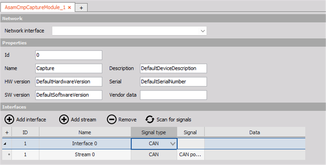
Figure 4. Network selector and a manual mapping.
Adapter labels depend on the runtime environment. Identify the intended physical adapter before operation; the label alone in this example does not establish its network connection.
Selecting an adapter defines the Ethernet path used by the capture module. Connecting a source can begin transmission immediately in the upstream implementation, so choose the intended network before completing mappings. Source: openDAQ capture-module usage
4. Set capture module properties
Use Properties to identify the capture module.
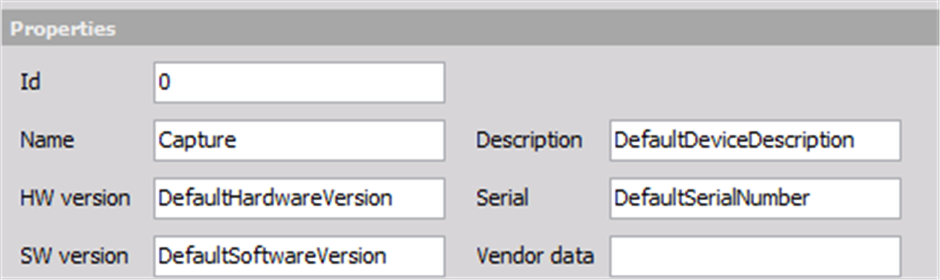
Figure 5. Device identity and descriptive properties. The displayed Default… strings are initial values.
| Field | What to enter |
|---|---|
| Id | Capture module device identifier. Coordinate it with the receiver and other capture modules. |
| Name | A descriptive name; the initial value is Capture. |
| Description | Description of the device or measurement role. |
| HW version | Hardware revision information. |
| SW version | Software revision information. |
| Serial | Device serial identification. |
| Vendor data | Additional vendor-defined information, if needed. |
Device IDs must be unique on the CMP network. Keep interface IDs unique within a capture module and stream IDs unique within an interface. The upstream module uses description, serial, hardware/software versions and vendor data in capture-module status messages. Source: openDAQ module structure
The automatically generated labels Interface 0 and Stream 0 are names. ID cells should be used when coordinating the transmitted identifiers.
5. Configure interfaces and streams manually
Create an interface
- Click Add interface.
- Expand the interface with the small triangle in the first column if necessary.
- Edit the interface’s ID and Name.
- Open its Signal type dropdown menu.
When first interface is added, also its first child stream is added automatically.
The interface’s Signal type list offers:
| Option | Use |
|---|---|
| Undefined | Initial/unspecified payload type; select the required concrete type before use. |
| CAN | A compatible CAN source. |
| CAN FD | A compatible CAN FD source. |
| Analog | A compatible analog source. |
| Ethernet | A compatible Ethernet source. |
Assign a source to a stream
- Select the child stream’s Signal cell, initially NoSig.
- Click to open the dropdown menu.
- Choose the required signal.
- Check the resulting Signal and Data cells.
In this example you can see CAN port 1–4, CAN encoded signals, CAN port statistics, system memory/CPU signals, and storing status signals.
The stream’s Signal type cell is read-only and follows its parent interface.
Add more streams
- Select the interface row.
- Click Add stream.
- Set the new stream’s ID and name.
- Assign its source in the Signal cell.
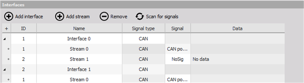
Figure 6. A second stream under Interface 0. It starts unassigned. Select the parent interface before adding a stream.
To remove an entry, select its row and click Remove in the Interfaces section. Review the selected row carefully, especially when selecting an interface containing child streams.
6. Scan for signals
Use Scan for signals to populate mappings from sources available on the selected device.
- Configure the device’s source channels first.
- Open the CMP capture module.
- Click Scan for signals.
- Review every generated interface and stream.
- Adjust identifiers, names and signal types as required.
- Remove unwanted or duplicate mappings.
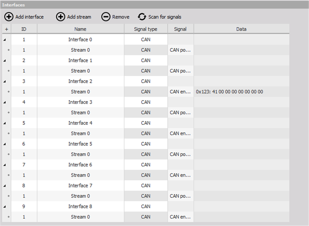
Figure 7. Example scan results on the four-port CAN device. Source names are shortened by the narrow Signal column; the source menu shows their full names.
In this example, scanning added eight interfaces with CAN source mappings, alongside the manually created interface. It included both CAN port and CAN encoded sources.
One CAN encoded stream displayed:
0x123: 41 00 00 00 00 00 00 00
This is the payload preview observed in the example. It is not a required message ID or fixed value.
7. Check and use the configuration
Before using the configuration:
- Confirm the intended module instance is Used.
- Confirm the Network interface is selected.
- Review capture module, interface and stream IDs.
- Confirm each required stream has a compatible source rather than NoSig.
- Check source activity and the Data preview where available.
- Confirm the receiving system sees the expected CMP traffic and identifiers.
A populated Data cell confirms that the configuration view can show source data. It does not by itself confirm that packets reached the receiving system.
The device toolbar provides Start, Stop, Save and Save as. Start/stop operation as required by the device workflow, and save the device configuration when you want to retain the setup. CMP forwarding and recording a Dewesoft data file are separate operations; configure Storing separately if local recording is also required.
8. Troubleshooting
| Symptom | Check or action |
|---|---|
| Module is missing from the toolbar | Select the device in Config, then add CMP capture module through More…. |
| No interfaces are listed | Use Add interface for manual setup or Scan for signals for device sources. |
| Add stream does not create the intended child | Select the parent interface row, then click Add stream. |
| Signal shows NoSig | Open the stream’s Signal cell and assign a compatible source. |
| Data shows No data or remains blank | Confirm source activity and compatible Signal type. A source assignment alone does not prove data is flowing. |
| A stream’s Signal type cannot be edited | Change the parent interface’s Signal type; the child inherits it. |
| Scan creates duplicate sources | Review appended mappings and remove unwanted rows. |
| Receiver sees no CMP traffic | Check Used, adapter selection, physical network, source activity, receiver configuration and matching IDs. |
| Packet-capture support fails on Windows | Check the upstream Npcap prerequisite, including WinPcap API-compatible installation mode. |
| A source name is shortened | Open its Signal cell menu to inspect the full available names. |
| Multiple similarly named sources appear | Confirm which physical port or encoded source is intended before assigning it. |