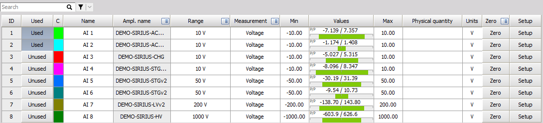
Channel Grid
Channel grid is a tabular view of input or output channels, depending on the module you select.
Search and Filter
You can use the Search box and Filters to find specific channels. Even if a column is hidden, the filter will still work.
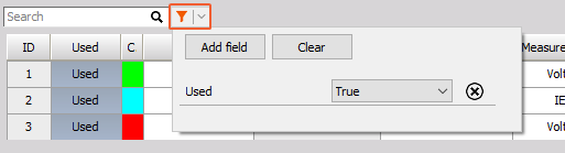
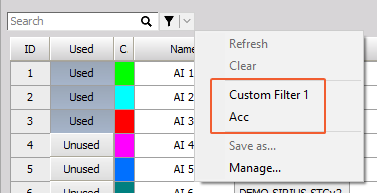
After setting a filter up, save it for future use by clicking Save as… in the dropdown menu.
NOTE: Filters are currently only available in Analog In and Channels grids.
Edit Columns
Right click on any column title and select Edit columns. Use checkboxes to select what to show/hide, or reset the grid to default settings. Click on a property to change it once displayed.
- ID
- Measurement unit
- Used, Stored, Exported
- Transferred, Stored on client
- Color
- Sample rate, Transfer rate
- Name, Description, Tags
- Amplifier info, Amplifier name
- Amplifier S/N, Device S/N, System S/N - Serial numbers.
- Range
- Dual core - Activate dual core mode. Only with dual-core amplifiers.
- Excitation
- LP filter, LP filter type, LP filter order
- HP filter
- Measurement - Type of measurement (Voltage, IEPE, Charge,…), Input type
- Min, Values, Max
- Crit low/high, Warn low/high, Add alarm events, Hysteresis (value), Hold time (s)
- Physical quantity, Units
- Scale - Linear scaling. For nonlinear scaling: Analog sensors editor
- Sensitivity
- Elec. scale units
- Offset, Offset in amplifier unit
- Scaling
- Sensor model, Sensor S/N
- Bias Voltage (V)
- TEDS user data, TEDS serial number, TEDS Scan
- Enabled - When disabled, all amplifier functions (Excitation, TEDS scan, etc.) are inoperative to ensure safety (currently available for SIRIUS DualCore-STG and HS-LV amplifiers).
- Unique ID
- Sensor calibration date, Sensor recal date, Sensor check target, Sensor check result, Sensor check error, Shunt calibration auto target, Sensor manufacturer
- Device display name
- Bridge mode, Bridge resistance, Bridge shunt type, Bridge active leg, Poisson ratio, Youngs modulus, Gage factor
- Leadwire compensation - Input resistance value for compensation of lead wires.
- Sensor unbalance - You can input it manually or measure it in Channel setup.
- Self-test error - Measured error.
- Zero - This button automatically zeroes out the channel, Zero Target - Displays Zero target value.
- Group
- Setup - Opens Setup menu.
ID
ID column indicates the number of the channel. It usually starts with 1 and counts up to the maximum number of available module outputs.
This column is a direct reference to the slots within your system.
NOTE: If you have a Dewesoft Sirius system, the first 8 modules are the ones on the mainframe itself.
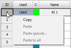
This field has also a copy/paste function. When you right-click on a slot number, a window will appear:
Example: several channels (e.g. 1, 2 and 6) contain the same module with the same sensor connected. If you click now on slot 0 and select Copy, the system will remember all the important settings from channel 0, like amplifier type, input and filter ranges, units, calibration and zero settings. Now click on slot 2 and select Paste - this will copy all settings from channel 0 to channel 2 and so forth with other same modules. You can also paste the channel parameters from one slot to multiple slots at once.
Paste special will be given additional options to select a region from where to where the selection will be pasted.
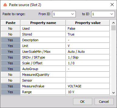
It will also show the properties which will be pasted and give the user a chance to paste only selected properties by clicking on Yes / No button left to the name of properties. Selection will be stored for the next use of the Paste special function.

WARNING: This function is working best with amplifiers of the same type. Properties which are not possible to set will be ignored. Channel names will not be copied.
Amplifier Name
Shows the name of the module and the range selected.
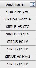
A small arrow on the right side of the field is running through all fields, indicating that all channels are scanned for new amplifiers or settings.

When you click on one of the Amplifier columns header line (with), a selection field will appear. In this field you can choose from different options which will have an effect on all available channels

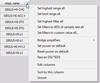
For all modules, there is an option to Set PowerOnDefault option. This will keep the current settings of the modules when power is switched off. Reset PowerOnDefault (DAQP only) resets settings to factory default.
If the module is removed from the system during operation, it will turn to a red color. Clear not found modules option will remove all the modules from the list which are not found (all modules in red color).
- Set highest range - will set the range of all amplifiers to the highest possible input range.
- Set best range - will measure the real-time data and set the range of all amplifiers to the best possible fit.
- Set highest filter - will set the analog input filter to the highest possible values or switch it to off, if possible.
- Set filters to 40% of the sample rate - will set the analog input filter to the nearest value of the Nyquist frequency (40% of sample rate) to prevent aliasing.
- Set filters to custom value - will open the dialog and allow the user to enter the value to set the filter to it.
- Fill rack option - will enable an option to start adding modules to the system.
When there is at least one special module, there are more options available which help to work with these modules.
If anti-aliasing filters (AAF prints) are selected, the drop down will show also the option for setting these filters to either bypass or any available low pass filte range.
- Bridge zero - which zeroes the bridge by hardware.
- Amplifier zero - resets this zero value that it has no offset.
- Short on for 2s - shortens the modules for two seconds while
- Shunt on for 2s - switches on the shunt of the bridge module for two seconds.
These options help to quickly see that bridge modules are connected and working correctly.
The options for zero, shunt and short are available also from the Channel setup, short and shunt are available also during the Measurement to determine the start and end offset of amplifiers.
If any Charge modules are installed, the drop-down will give the option to reset the modules. If any FreqA modules are found, there is an option to find the correct analog trigger levels for all the modules.
- Clear not found modules option will remove all amplifiers which are marked in red in the channel list (which were found once, but couldn’t be found anymore) because the amplifier was removed from the system or from any additional reason.
- Disable amplifier option will disable the currently selected amplifier. It means that it will not search for the amplifier at this address.
- Rescan TEDS sensors will scan again the TEDS sensors for amplifiers where the SCAN interferes with data acquisition (IEPE amplifiers).
Sensors and TEDS sensors
For each analog channel, a sensor can be predefined in the Sensor database and used in the Channel setup for an individual channel. To notify that the sensor is used, the sensor name and serial number are shown instead of the module range.
The same column shows the TEDS sensors if there are any attached to the amplifier. TEDS sensors are sensors with a built-in chip which automatically sends the information like scaling and serial number to the amplifier. This is shown as TEDS sensor in the same place as a user-defined sensor.
Values
Contains a dynamic representation of this input channel, as well as the units of measurement and description, and the scale.
All this can be set in Channel setup column, which can be reached by double click on channel cell in this column.
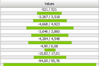
NOTE: When the input signal exceeds the possible range, a red indicator Overload will be displayed.
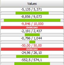
If this happens, check your sensor and/or select another input range (in Channel setup).
By clicking on the PHYSICAL VALUES caption, a drop down which values are shown is displayed. Normally Display measured values is selected. In the case when we have bridge amplifiers, there are additional option to display bridge balance or shunt calibration values.
Zero
This is a button that you can click to perform a mathematical zeroing of this input, to offset small variations in the zero position of the input.
Press the left mouse button to activate zeroing, and the right mouse button to deactivate it (reset to default input range).

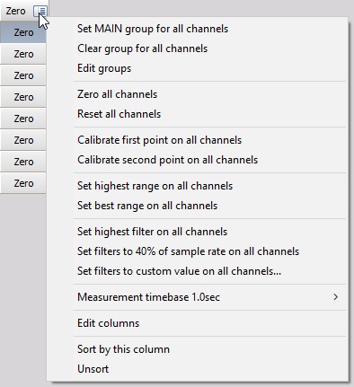
- Zero all AUTO channels option will perform a channel zero for all channels set to auto.
- Reset all AUTO channels will set zero offsets to all channels.
- Calibrate the first point on all AUTO channels option allows calibrating all the channels at once.
Usually, this is useful when the CAL signal is available on all the inputs. If we have the option to put electrical 0% and for example 80% on all the channels, we can enter the 0 as the first point in the channel setup and 80% as the second point in the Channel setup for each channel, set all the channels to AUTO and then first apply 0%, press Calibrate first point, then apply 80% and press Calibrate Second point on all AUTO channels.
- Highest and best range selection works the same as for all channels (selectable from Amplifier section), but only on specific channels set to Auto.
- We can also choose the Calibration time base as 0.1 sec (Ave) or 1.0 sec (Ave) (same as in Channel setup). 0.1 second will give faster response time while 1 second will provide more averaging time to perform calibration.
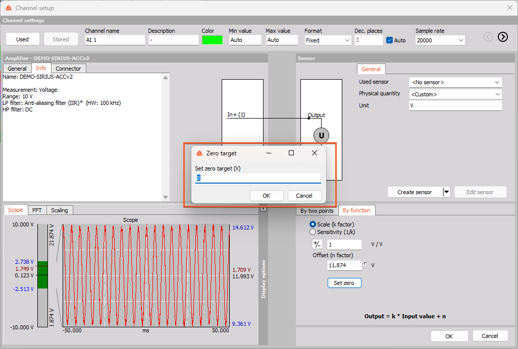
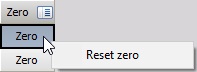
Set custom zero target
To set custom zero target please right click on the Set zero button in the Channel setup:
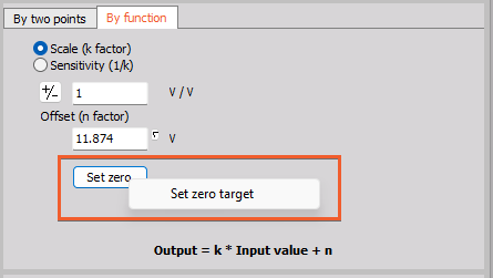
Now you can add the desired custom target for zeroing: