TRDP Train Realtime Data Protocol — User manual
1. Opening the module
Select the device in the device tree, open Config, and choose More… → TRDP. The TRDP page contains a decoder tab, network interface selection, frame definitions, and diagnostic statistics.
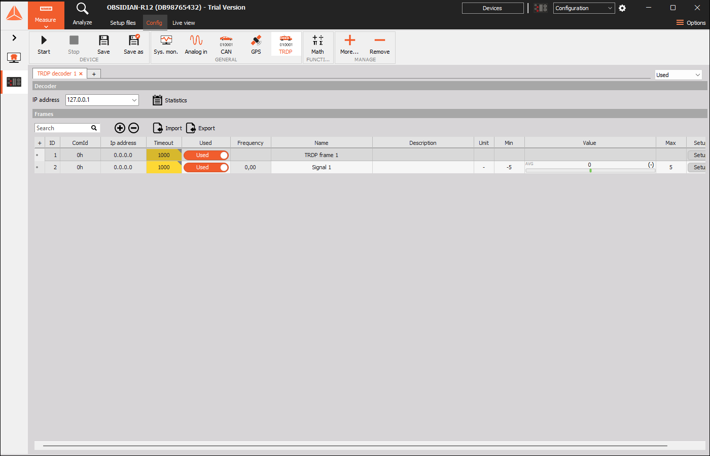
2. Decoder instances
Each decoder appears as a tab, for example TRDP decoder 1.
| Control | Function |
|---|---|
| Decoder tab | Selects the decoder whose interface and frames are being configured. |
| + beside the tabs | Adds another decoder instance. |
| × on a decoder tab | Removes that decoder instance. |
| Used / Unused | Enables or disables the selected instance. |
| IP address in the Decoder section | Selects the local network address used by the decoder. |
| Statistics | Opens the TCN statistics window. |
Choose the local address belonging to the network connected to the TRDP equipment. 127.0.0.1 is the loopback address; use the appropriate network interface address for communication with external equipment.
The decoder IP address and the IP address inside an individual frame are separate settings: the first selects the local interface, while the second belongs to that frame’s communication definition.
3. Managing frame definitions
The Frames section lists configured frames and their signals.
| Control | Function |
|---|---|
| + above the grid | Adds a frame and opens Frame setup. |
| − above the grid | Removes the selected item. Select the intended row before using it. |
| Search | Filters the grid to locate a definition. Clear the search to show the full list. |
| Import | Opens a JSON definition file. |
| Export | Saves definitions to a JSON file. |
| Setup in a row | Opens the editor for the corresponding definition. |
| Used | Enables or disables the corresponding frame or signal. |
The grid includes ID, ComId, IP address, Timeout, Used, Frequency, Name, Description, Unit, Min, Value, Max, and Setup. Use the horizontal scrollbar when columns extend beyond the window.
Name, Description, Unit, Min, and Max are editable for signal rows. The Value column shows the channel value; the signal’s Frequency column provides a rate indication. The Min and Max fields describe the channel display range, separately from the signal’s bit length and data type.
Import and export
- Use Export to save a frame-definition file with the .json extension.
- Use Import and select a compatible JSON file to load definitions.
- Review the decoder interface, frame addresses, ComIds, payload layout, and signal assignments after importing.
- Save the device setup when the configuration is ready.
The JSON file carries frame definitions. Save and Save as in the device toolbar manage the device setup.
4. Frame setup
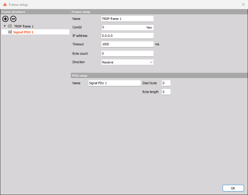
The editor has a Frame structure tree on the left and settings for the selected item on the right. A typical structure is:
TRDP frame
└── Signal PDU
    ├── Signal 1
    └── Signal 2
Select the frame to edit frame settings, a PDU to edit its payload region, or a signal to edit its interpretation.
| Setting | Function |
|---|---|
| Name | Descriptive name for the frame. |
| ComId | Communication identifier matching the intended TRDP data. |
| hex | Switches the ComId numeric entry representation. |
| IP address | Network address associated with the frame. Match it to the intended communication configuration. |
| Byte count | Frame payload size in bytes. |
| Direction | Selects Receive or Transmit. |
The same ComId and payload layout must be understood by the communicating equipment. Use addresses and sizes from the equipment’s communication definition; the initial zero values shown in an empty editor are fields to configure.
Receive
Choose Direction → Receive to decode incoming data into channels.
Timeout is entered in milliseconds. Set it according to the expected arrival interval and the allowed interruption in communication. For example, 1000 ms corresponds to one second.
Receive configuration exposes Timeout. Transmit configuration exposes Frequency instead.
Transmit
Choose Direction → Transmit to build outgoing frames.
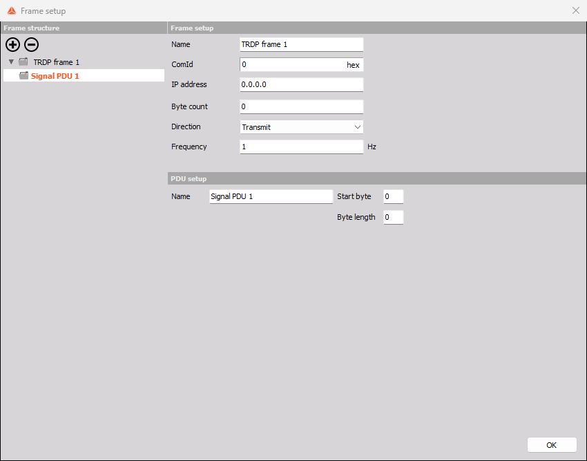
Frequency is entered in Hz and sets the frame transmission rate. A frequency of 10 Hz corresponds to a nominal period of 100 ms. Configure the frame IP address for the intended destination.
Each transmitted signal also needs an input source, described in Section 7.
5. PDU structure
A Signal PDU groups signals within a defined byte region of a frame.
| Setting | Function |
|---|---|
| Name | Names the PDU in the structure tree. |
| Start byte | Sets the PDU’s starting byte position within the frame payload. |
| Byte length | Sets the size of the PDU region. |
To add another PDU, select the frame in Frame structure, press the tree’s +, and choose Signal PDU. To add a signal, select its parent PDU and press +. Use the tree’s − to remove the selected structure item.
Keep each PDU within the frame’s Byte count and each signal within its PDU. When several PDUs or signals share a frame, check their positions and lengths against the payload specification.
6. Signal decoding and representation
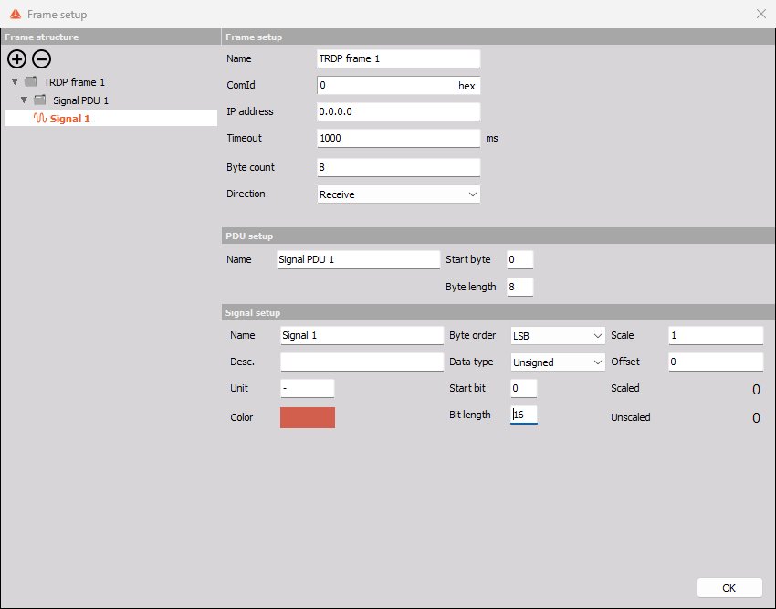
Select a signal in Frame structure to show Signal setup.
| Setting | Function |
|---|---|
| Name | Channel name. |
| Desc. | Description of the signal or its meaning. |
| Unit | Engineering unit displayed with the channel. |
| Color | Display color associated with the signal. |
| Byte order | LSB or MSB, matching the payload’s byte ordering. |
| Data type | Unsigned, Signed, Float, or Boolean. |
| Start bit | Starting bit position for the signal in the PDU layout. |
| Bit length | Number of bits assigned to the signal. |
| Scale | Multiplicative factor for engineering conversion. |
| Offset | Additive term for engineering conversion. |
| Unscaled | Preview of the raw signal value. |
| Scaled | Preview of the converted signal value. |
Byte order and data type
LSB uses least-significant-byte ordering and MSB uses most-significant-byte ordering. Match the sender or receiver definition.
| Data type | Intended interpretation |
|---|---|
| Unsigned | Integer values without a sign. |
| Signed | Integer values that can represent negative and positive numbers. |
| Float | Floating-point values. Match the bit length to the defined format. |
| Boolean | Logical state. Match its position and width to the payload definition. |
A mismatched byte order, type, or bit position can produce plausible-looking but incorrect values. Verify the interpretation against a known reference value.
Scaling
For received numeric signals, the engineering conversion is:
Scaled value = Unscaled value × Scale + Offset
For example, a raw value of 1234, a scale of 0.1, and an offset of −40 represent 83.4 engineering units.
Use the scaled and unscaled previews to check the conversion. The Unit field labels the result; it does not replace the scale and offset settings.
7. Transmit signal inputs
In a transmit frame, Signal setup includes an Input selector.
| Input | Purpose | Additional controls |
|---|---|---|
| Constant | Sends a fixed numeric value. | Value |
| Raw hex | Provides a hexadecimal input value. | Value |
| Signal | Uses a device signal as the source. | Signal, Type, and evaluation controls when applicable |
| Counter | Uses a counter input. | Min, Max |
Signal position, bit length, byte order, data type, scale, and offset remain part of the definition. Ensure the chosen source and its range fit the assigned payload field.
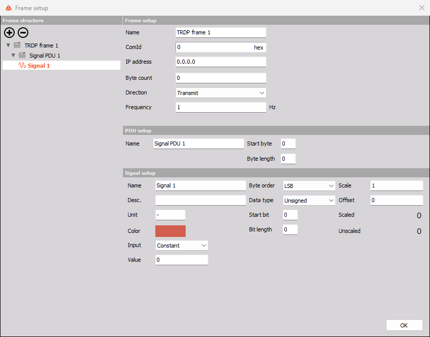
Constant
Choose Constant and enter the required Value.
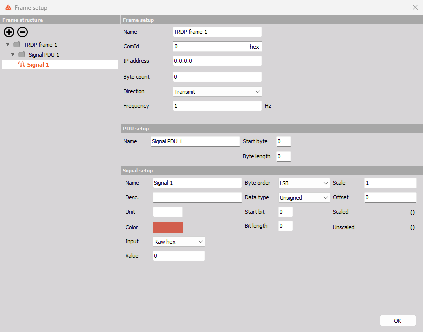
Raw hex
Choose Raw hex and enter the required hexadecimal Value. This mode is useful when the specification gives a raw field value in hexadecimal notation.
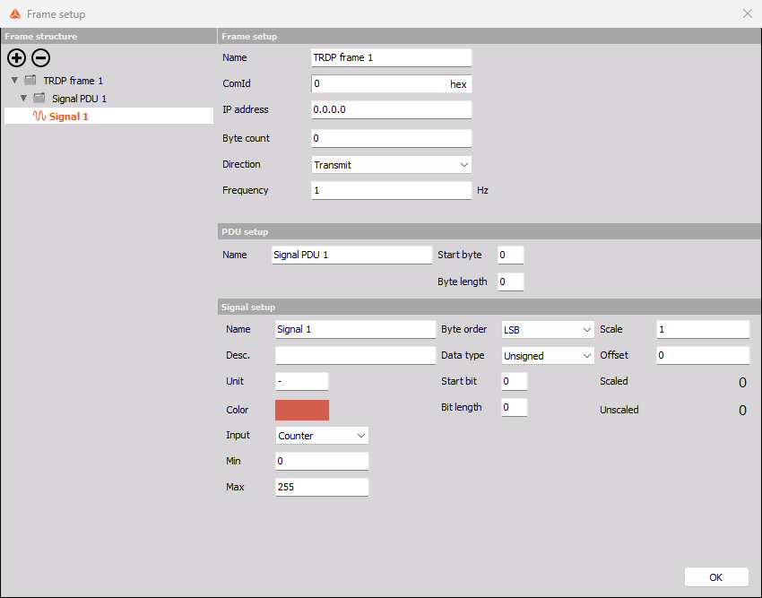
Counter
Choose Counter and configure Min and Max for the counter range. The initial controls show 0 and 255. Set the range to fit the receiving equipment’s expected counter field and the configured bit length.
Signal
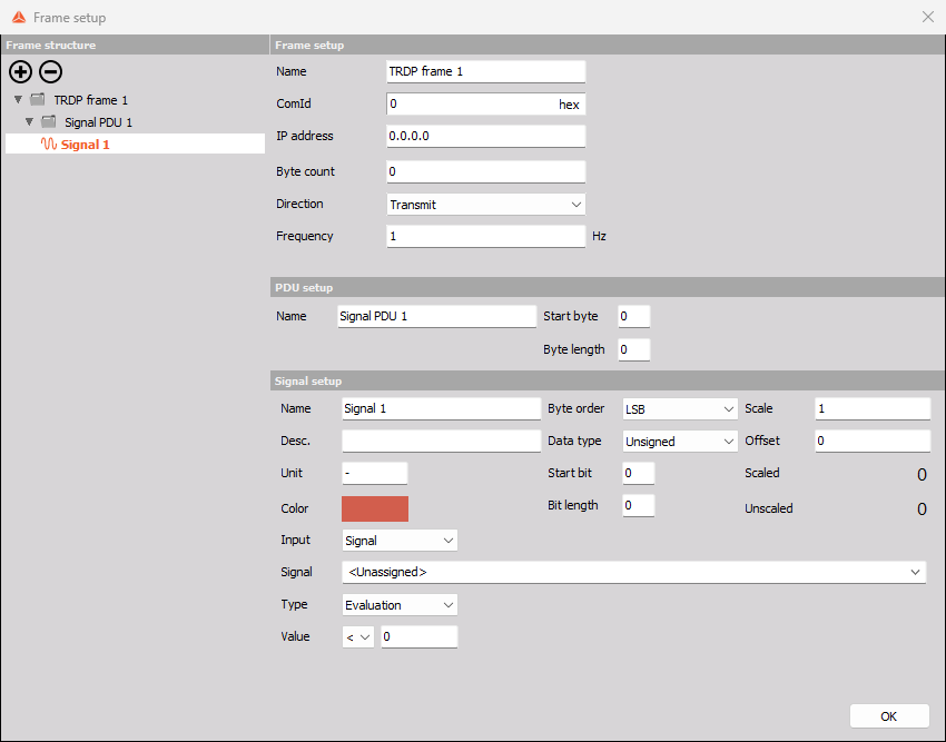
Choose Signal, then select a source in the Signal list. The available choices depend on the signals present in the device setup. Replace
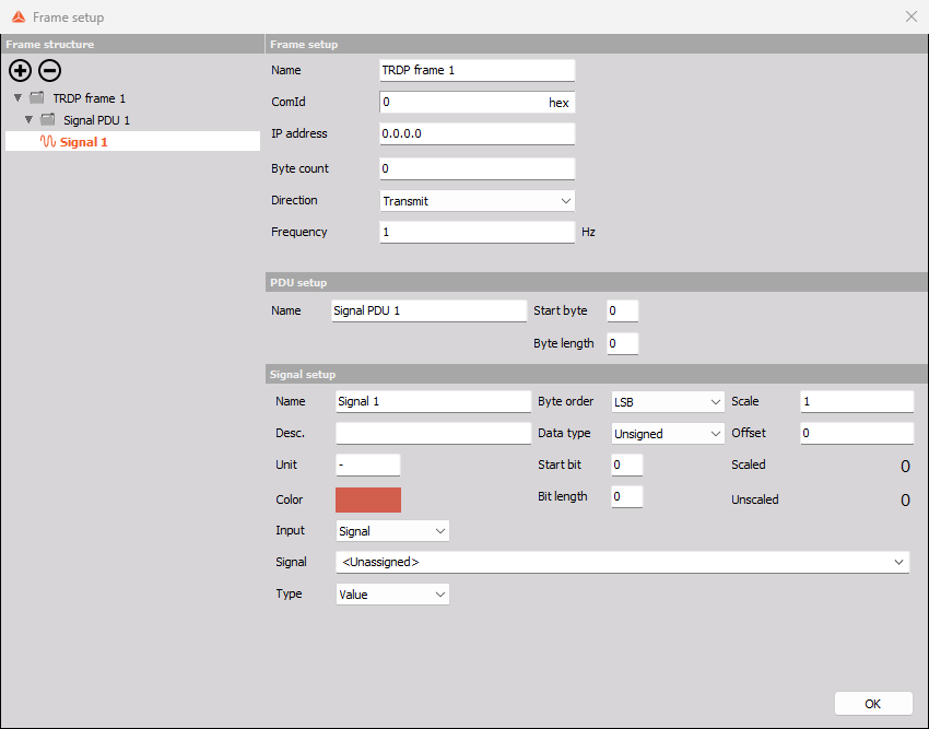
The Type selector offers:
| Type | Function |
|---|---|
| Value | Uses the selected signal’s value. |
| Evaluation | Evaluates the selected signal against one comparison value. |
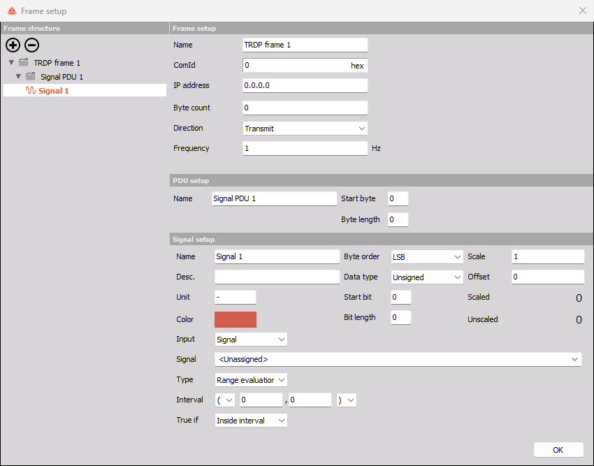
| Range evaluation | Evaluates whether the signal is inside or outside a configured interval. |
Evaluation
Choose Type → Evaluation, select the comparison operator, and enter the comparison value.
Available operators are <, ≤, =, ≠, ≥, and >. For example, choosing > with a value of 50 defines the condition “source signal greater than 50.”
Range evaluation
Choose Type → Range evaluation, enter both bounds, and select True if → Inside interval or Outside interval.
The brackets control whether the boundary values are included:
| Notation | Meaning |
|---|---|
| [a, b] | Includes both bounds. |
| (a, b) | Excludes both bounds. |
| [a, b) | Includes the first bound and excludes the second. |
| (a, b] | Excludes the first bound and includes the second. |
For example, [10, 20] with Inside interval is true from 10 through 20, including both endpoints.
8. Communication statistics
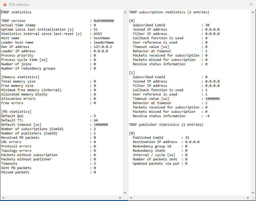
Select Statistics in the Decoder section to open TCN statistics. The window contains general statistics on the left and subscription/publisher details on the right. Scroll within the panes to inspect additional information.
General statistics
The general pane includes:
- TRDP version, timestamp, uptime, and statistics interval.
- Host and leader information, own IP address, and leader IP address.
- Process priority and cycle time.
- Join and redundancy group counts.
- Memory size, free memory, allocation information, and memory errors.
- PD statistics, including default QoS, TTL, timeout, subscription count, and publisher count.
- Received and sent PD packets, CRC errors, protocol errors, topology errors, packets without a subscription or publisher, timeouts, and missed packets.
Subscription details
Each subscription entry includes its Subscribed ComId, joined IP address, filter IP address, timeout in microseconds, timeout behavior, received packet count, missed packet count, and receive status information.
The frame editor uses ms for timeout, whereas statistics display µs. Thus 1000 ms = 1,000,000 µs.
Publisher details
Each publisher entry includes its Published ComId, destination IP address, redundancy group and state, interval/cycle in microseconds, packet count, and update count.
Use the publisher interval and sent packet counter to inspect transmission activity. Use subscription packet counts and timeout information to inspect reception.
9. Receive configuration workflow
- Select the device and open Config → TRDP.
- Set the decoder’s IP address to the intended local interface.
- Press the Frames +.
- Enter the frame name, ComId, IP address, and payload byte count.
- Select Receive and set Timeout in milliseconds.
- Select the PDU and define its start byte and byte length.
- Add signals beneath the PDU.
- Configure each signal’s bit position, length, byte order, type, scale, offset, name, and unit.
- Confirm with OK and check the required Used controls.
- Use Save or Save as to retain the device setup.
- Use Start in the device toolbar to run acquisition, then inspect the signal values in Live view and communication activity in Statistics.
For an eight-byte payload with one PDU covering the complete payload, set Byte count = 8, PDU Start byte = 0, and PDU Byte length = 8. A 16-bit unsigned signal at Start bit = 0 occupies the first two bytes; its byte order and scaling must match the sender.
10. Transmit configuration workflow
- Select the correct decoder interface and add a frame.
- Enter the frame’s ComId, destination IP address, and payload byte count.
- Select Transmit and set Frequency in Hz.
- Define the PDU region and add its signals.
- Set the layout and representation of every signal.
- Choose Constant, Raw hex, Signal, or Counter for each input.
- For Signal, assign the source and select the required value or evaluation type.
- Confirm with OK, enable the required items, and save the device setup.
- Use Start to run acquisition and inspect publisher packet counts in Statistics.
Use Stop in the device toolbar when acquisition should stop.
11. Troubleshooting
| Symptom | Settings and information to inspect |
|---|---|
| No received values | Decoder interface, frame IP address, ComId, Used state, device acquisition state, and subscription packet counts. |
| Increasing timeout count | Expected arrival interval, frame Timeout, matching ComId/address, and missed packet information. |
| Incorrect numeric values | PDU start byte, signal start bit, bit length, byte order, data type, scale, and offset. |
| Incorrect engineering units | Signal Unit, Scale, and Offset. |
| No transmitted data | Transmit direction, destination address, Frequency, enabled state, acquisition state, and publisher counters. |
| Transmitted signal has no source | Input → Signal assignment; replace |
| Evaluation changes at the wrong threshold | Comparison operator and value, interval bounds, inclusive/exclusive brackets, and Inside/Outside interval selection. |
| Definition is missing from the grid | Active decoder tab and the Search filter. |
| More than one configuration is needed | Add another decoder using the tab +, then configure its interface and frames. |