AC power function block
The AC power function block calculates AC power directly on the device in standalone/RT mode. It uses voltage and current channels from the Analog in module and produces the power values at the end of each calculation interval, which you define with the number of periods. Currently you can enable the AC power function block in combination with the following devices:
- SIRIUS-XHS
- OBSIDIAN
- IOLITE-X
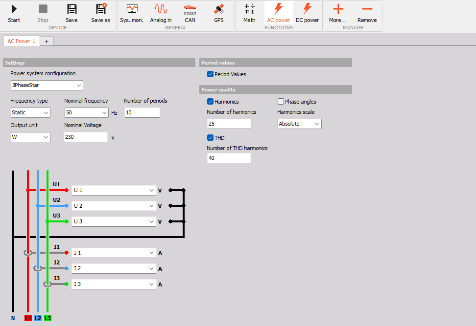
Adding the function block
The AC power function block is added in the Config view under More… -> Add module -> AC power. Every new function block opens in its own tab (AC Power 1, AC Power 2, …). To add another AC power calculation, press the + tab. To delete the selected function block, press Remove.
Settings
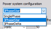
- Power system configuration - defines the type of the measured power system. The wiring diagram and the number of voltage and current channels change according to the selected configuration:
- SinglePhase - one voltage and one current channel (L1 and N).
- 3PhaseStar - three phases with neutral (L1\, L2\, L3 and N)\, three voltage and three current channels. Voltages are measured between each phase and the neutral.
- 3PhaseDelta - three phases without neutral (L1\, L2\, L3). Voltages are measured between the phases.
- Frequency type - defines how the frequency of the power system is determined:
- Static - the power system has a fixed frequency\, defined with the Nominal frequency (in Hz). The nominal frequency can be selected from the preset values in the drop-down list or freely entered.
- Variable - the frequency of the power system changes during the measurement (e.g. motor drives). Instead of the nominal frequency\, you define the Frequency limits - the lower and upper frequency in Hz.

- Number of periods - defines over how many periods of the base frequency the values are calculated (default is 10 periods at 50 Hz which gives a calculation interval of 200 ms\, i.e. 5 values per second). With Variable frequency type\, the length of the calculation interval follows the measured frequency. NOTE: The number of periods does not set the sample rate. The input channels are still acquired at the sample rate set on the device\, and the number of periods only sets how often the result is calculated.
- Output unit - the unit of the calculated power. The user can choose between W, kW and MW.
- Nominal voltage - the nominal voltage of the power system in V (default value can be changed in settings).
Period values
- Period values - when enabled\, the function block also calculates the values for every single period\, in addition to the values calculated over the defined number of periods.
Power quality
- Harmonics - when enabled\, the function block calculates the harmonics of the voltage and current channels.
- Number of harmonics - the number of calculated harmonics.
- Harmonics scale - defines how the harmonics are expressed:
- Absolute - the harmonics are given in the unit of the input channel.
- Relative - the harmonics are given in %.
- Phase angles - when enabled\, the phase angles of the harmonics are calculated as well.
- THD - when enabled\, the function block calculates the total harmonic distortion of the voltage and current channels\, expressed in %.
- Number of THD harmonics - the number of harmonics used in the THD calculation.
Channel selection
The wiring diagram shows how the voltages and currents are measured on the power lines (L1, L2, L3 and N, depending on the power system configuration):
- U1, U2, U3 - select the voltage channels from the drop-down lists. In star and single-phase configuration the voltages are measured between each phase and the neutral\, in delta configuration between the phases.
- I1, I2, I3 - select the current channels from the drop-down lists. The currents are measured on each phase.
Only channels that are selected as used in the Analog in module will be available in the drop-down lists.
Output channels
The function block creates the following output channels, calculated at the end of each calculation interval:
Per-phase values (the suffix _1, _2, _3 marks the phase; the number of phases depends on the power system configuration):
- U_rms\, I_rms - RMS value of the voltage and current in V and A.
- U_rm\, I_rm - rectified mean value of the voltage and current in V and A.
- U_H1\, I_H1 - voltage and current of the first (fundamental) harmonic in V and A.
- P, Q, S - active\, reactive and apparent power in the selected output unit.
- P_H1\, Q_H1\, S_H1 - active\, reactive and apparent power of the first harmonic.
- PF, cos_phi, phi - power factor\, cos φ and phase angle φ between voltage and current.
- phiU - voltage phase angle of phases 2 and 3 (relative to phase 1).
Average values of all phases (_(avg)):
- U_rms\, I_rms\, U_rm\, I_rm\, U_H1\, I_H1 - the average of the per-phase values over all phases.
Total values of the power system:
- P, Q, S - total active\, reactive and apparent power.
- P_H1\, Q_H1\, S_H1 - total active\, reactive and apparent power of the first harmonic.
- PF\, cos_phi_h1 - total power factor and cos φ of the first harmonic.
Other channels:
- Frequency - measured frequency of the power system in Hz.
- Status - status of the calculation.
- THD_U\, THD_I - total harmonic distortion of the voltage and current per phase in %. These channels are available only when the THD option is enabled.
- U_H\, I_H - voltage and current harmonics per phase\, in the unit of the input channel (Absolute scale) or in % (Relative scale). These channels are available only when the Harmonics option is enabled.
- phi_U_H\, phi_I_H - phase angles of the voltage and current harmonics per phase. These channels are available only when the Phase angles option is enabled.
- Period values (channels with the suffix per) - the same voltage, current, power and power factor values, plus the Period frequency, calculated for every single period. These channels are available only when the Period values option is enabled.
NOTE: In RT, run mode, you have no option to change the settings because all of them are locked.