Kistler RoaDyn 2000 Plugin
1 Introduction
The DEWESoft® RoaDyn 2000 LAN Plugin enables DEWESoft® to acquire data from the Kistler RoaDyn2000 measurement system via LAN. There are three operation modes:
- No AD card: The RoaDyn2000 is running as stand-alone
- Master-Mode: The RoaDyn2000 acts as clock provider for the AD card of the measurement system
- Demo-Mode: When no RoaDyn system is connected, DEWESoft® will create a virtual one
1.1 Links
DEWESoft homepage (http://www.dewesoft.com) you can download DEWESoft plugins when you go to: Support → Downloads → Plugins
1.2 Compatibility
The plugin is compatible with DEWESoft® X.
1.3 Files and Directories
The actual location of the directories on your computer may vary dependant on your computer’s locale settings and the settings you chose when installing DEWESoft®. For example: D:\DEWESoftX3\Bin\X3\Addons\
1.4 Licensing
The plugin requires a valid DEWESoft® license. To test the plugin you can use an Evaluation license.
1.5 Plug-in Installation
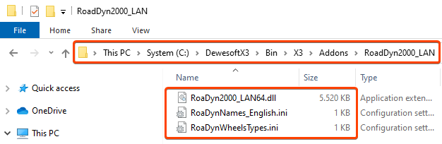
Simply extract the file RoaDyn2000_LAN.zip archive into the Addons folder of your DEWESoft® installation. (e.g. D:\DEWESoftX3\Bin\X3\Addons. Now your Addons folder should look like this:
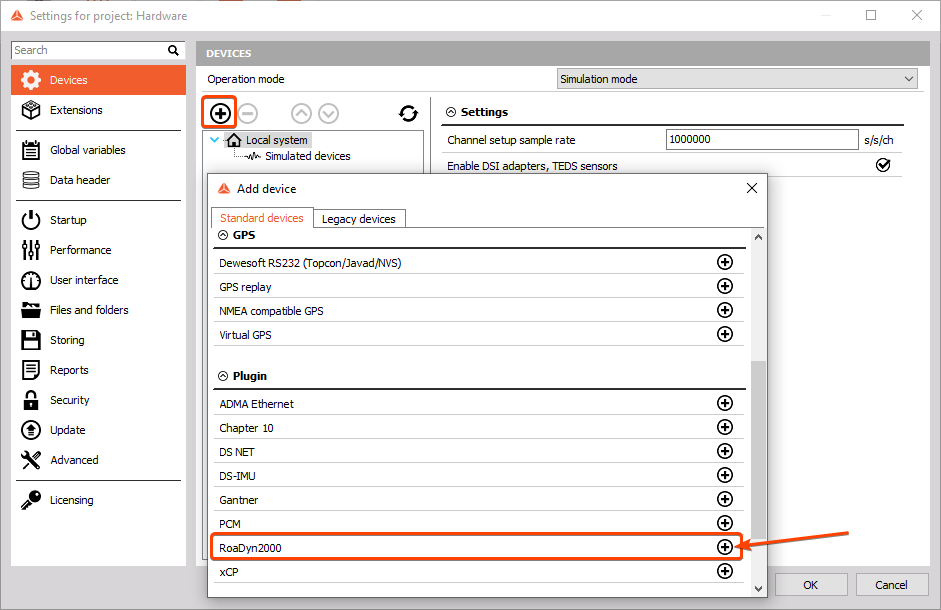
Then you can start DEWESoft® and register the plugin (aka. Extension). Click Options - Settings…, select Devices and click the plus sign. Then find the Kistler RoaDyn plugin in the list and activate it - when the plugin does not show up in the list, you may need to register it first.
2 Sensor connection
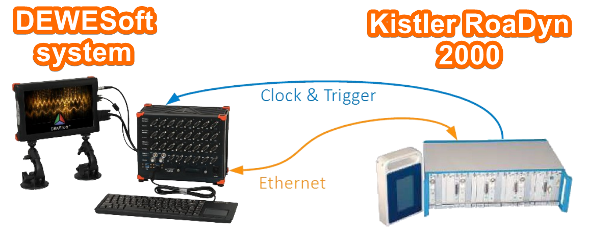
The sensors are connected to the measurement PC (e.g. S-BOX) via the LAN port (TCP/IP for data transfer). The clock and trigger lines of the sensor are connected to the corresponding clock and trigger pins of the sync connector on the DEWE-43 or SIRIUS measurement slice.
If more than one RoaDyn2000 system is connected it is recommended to use an Ethernet-Switch. Clock and trigger are daisy-chained between the RoaDyn systems.
3 Ethernet Configuration
The sensors are connected to the measurement unit via Ethernet cable for the data exchange. To establish a communication between the sensors and the measurement system, the Ethernet interface on the PC and the Ethernet interface/s on the sensor/s must be configured to use the same IP address range (i.e. the Subnet mask must match).
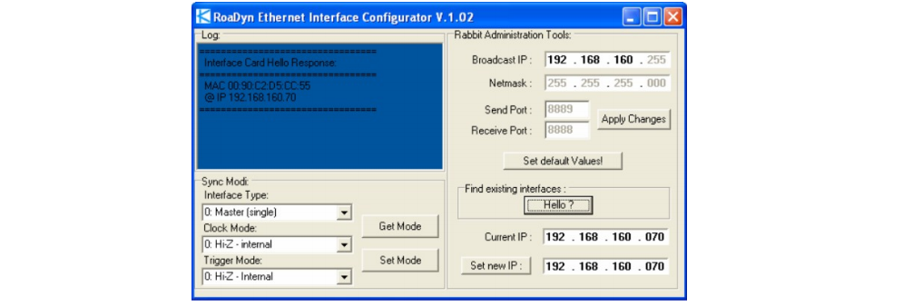
Configuration of the sensors Ethernet interface:
To configure the Ethernet interface of the sensors use the Kistler RabbitConfig tool provided with the sensors. With this tool you can also check if the communication to the sensors is working. When clicking the ”Hello?” button you should get a response from the network interface (MAC and IP address).
If you do not know the IP address of the RoaDyn2000 you can find it out by using the external control display: In the setup screen, click on Diagnostics then on Interface where you will find the currently set IP address and subnet mask.
4 Hardware Setup
After you have installed and enabled the plugin, start DEWESoft® and go to the Devices Setup:
4.1 Standalone Mode
When the RoaDyn2000 is connected to a DEWESoft® system without any AD card, the RoaDyn2000 will be configured as stand-alone system. Since no hardware synchronization is needed in this mode, you cannot (do not need to) connect the clock and trigger to the measurement system.
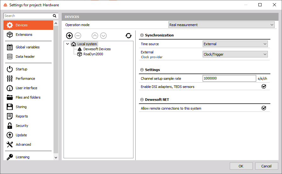
4.2 Master Mode
In Master mode, the RoaDyn2000 system acts as the clock master, providing clock and trigger for the DEWESoft® measurement slices.
In Master Mode it is important to set the DEWESoft® synchronization settings to External – Clock/Trigger:
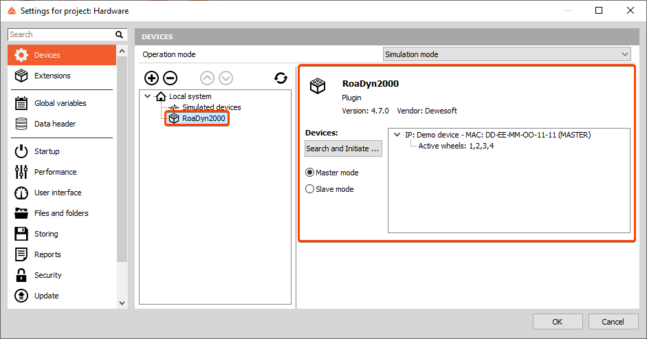
4.3 Demo mode
When no RoaDyn2000 system is found, DEWESoft® will create a virtual system denoted as “Demo device”. This is only to show the basic plugin functionality. No data is being simulated however.
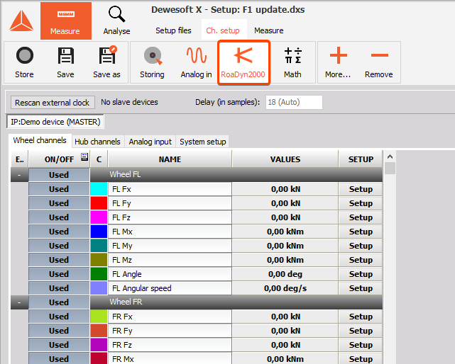
5 Channel Setup
In the channel setup of the Kistler RoaDyn plugin, you can activate/deactivate channels of the connected sensors.
- Dynamic acquisition rate: This is the sample rate and can be chosen between 80 Hz and 1250 Hz. Please note that the set sample rate will be valid after switching to Measurement mode (e.g. Overview).
- Delay: Due to the internal hardware of the RoaDyn2000 system, there is a delay between analogue data from the AD card and data from the RoaDyn2000 system. This delay is constant over time but depends on the set sample rate and the synchronization mode (Master or Slave mode). DEWESoft® will automatically set the correct delay, based on the selected sample rate and the synchronization mode.
- IP:192.168.xxx.xxx: If more than one RoaDyn2000 system is connected you can switch between the channel lists of each system.
- Channel list: The channel list of each system is divided into sub-groups (Wheel channels, Hub channels and Analog input) for easier navigation. A click on the Setup button next to each channel lets you alter each channels name, colour, unit and scaling.
- System Setup: The tab System setup let’s you choose the connected measurement wheel type and optionally assign the default channel names. It is also possible to change the default channel names and their units by editing the corresponding *.ini file.
6 Additional Settings
6.1 Settings in the RoaDyn2000_LAN.ini file
The hardware configuration of the RoaDyn2000 system is stored in the RoaDyn2000_LAN.ini file.
Usually it is not necessary to change any of these parameters because DEWESoft® handles the configuration automatically.
This file consists of the following parameters:
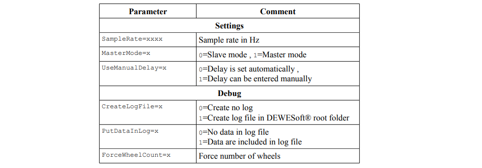
6.2 Changing the default names:
The files RoaDynNames_Deutsch.ini and RoaDynNames_English.ini are located in the DEWESoft® Addons folder.
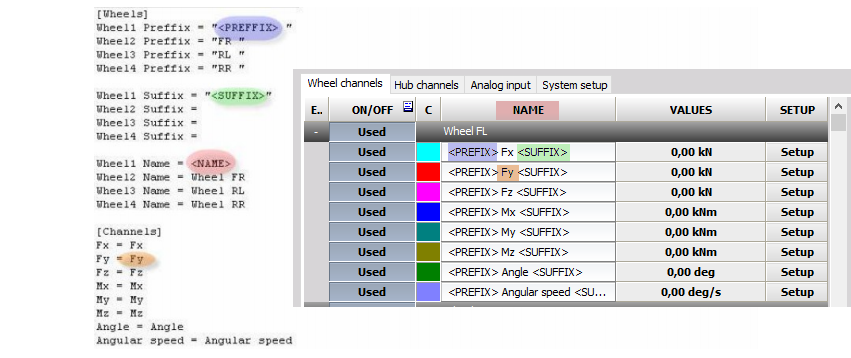
They store the default channel names for the system. You can change the default names in this file according to the syntax shown in the following picture. The default channel names can be loaded under the System Setup tab in channel setup.
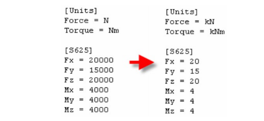
6.3 Changing the units
You can change the units and ranges of the channels by editing the RoaDynWheelTypes.ini file. This will affect all wheel types however.