The LORDMicroStrain Module enables Dewesoft to collect data from LORD MicroStrain wirelessgateways, which acquire the data from wireless sensor nodes. Extension requires Dewesoft X3 SP4 or higher.
We strongly recommend reading the Lord Microstrain manual from our web page:
System configuration
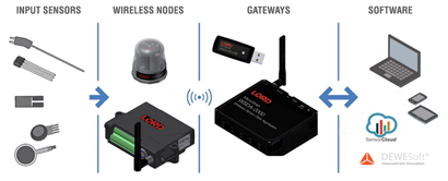
To assemble the whole measurement chain you need a sensor, wireless node, gateway and a PC.
WSDA wireless gateways coordinate communication between remote wireless sensor nodes and a local computer. The gateways can be connected via Ethernet or USB.
SensorConnect software installation
SensorConnect is a software where you can configure all the gateways, nodes and sensors. You can download SensorConnect here. More information about SensorConnect can be found on webpage and in Quick start guide.
WARNING: After configuring all the gateways and nodes in SensorConnect, please close the program, before opening Dewesoft. The gateway cannot communicate with both software at the same time.
Ethernet configuration
The gateways WSDA-1500 and WSDA-2000 are connected to the measurement PC (e.g. S-BOX) via the LAN port (TCP/IP for data transfer). If more than one gateway is connected, it is recommended to use an Ethernet Switch.
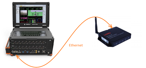
The gateway is connected to the measurement unit via ethernet cable for data exchange.
To establish a communication between the gateway and the measurement system, the ethernet interface on the PC and the ethernet interface/s on gateway/s must be configured to use the same IP address range (i.e. the subnet mask must match).
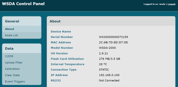
To find out the IP address of WSDA gateway visit WSDA Control Panel in Sensor Connect.
Open Network connection settings on your PC:
- Define the IP address (192.168.0.10)
- Define the Subnet mask (255.255.255.0)
- Click OK to confirm the settings

Open SensorConnect, select Add Device and enter devices IP address. After that, you will get a note that the device was added.

NOTE: For more information please refer to the LORD quick start guide or LORD Usermanual.
USB connection
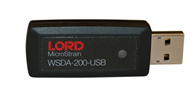
The gateway WSDA-2000 and WSDA-200-USB can be connected to the PC via USB connection.
When you connect the gateway via USB, it is automatically recognized by the SensorConnect software.
For more information, please take a look at WSDA-200-USB datasheet or WSDA-200-USB User manual.
Dewesoft LORD MicroStrain plugin
The LORD MicroStrain plugin enables Dewesoft to collect data from LORD MicroStrain wireless gateways, which acquire the data from wireless sensor nodes. There are three operation modes:
- No Dewesoft hardware: LORD MicroStrain is running stand-alone.
- Soft sync: Gateway and Dewesoft hardware each run with their own internal clock.
- Demo mode: When no gateway is connected, Dewesoft will create a virtual one.
Current plugin version: 2.1.4 [24.1.2020]
Minimum Dewesoft version: Extension requires Dewesoft X3 SP4 or higher.
Supported gateways:
Latest supported Visual C++ redistributable packages for Visual Studio 2017 is required before registering the addon.
License
Enable plug-in / Extension
Hardware setup
After you have installed and enabled the plugin, start Dewesoft and go to Settings -> Extensions.

The network can be run in synchronized or non-synchronized mode. Mixing synchronized and non-synchronized nodes is not allowed, all nodes work either in synchronized or non-synchronized mode. The network must be set to synchronized mode if nodes that return structure health data.
Gateways are added by (static) IP address. When the connection is established with the device, data is retrieved.
If you have an USB gateway, simply select Add USB gateway. The gateways will be automatically recognized.
To add a wireless node, select a gateway and insert the node address.
Demo mode
When no gateway is found, Dewesoft will create a virtual system denoted as “Demo gateway”. This is only to show the basic plugin functionality. A sine signal is simulated on every channel.
Channel setup
In the channel setup of the LORD MicroStrain plugin, you can activate/deactivate channels of the connected wireless nodes.

- If more than one gateway is connected, you can switch between the channel lists by selecting the gateway in the dropdown list.
- Channel list: The channel list of each gateway is divided by nodes into sub-groups for easier navigation.
- To change channel properties, enter Config mode.
- In Config mode it is possible to alter each channel name, colour, unit and scaling directly in the channel list.
- The supported sample rates depend on the wireless node.
- If a channel is enabled/disabled or the sample rate is changed the network bandwidth is updated.
- To apply changes, press the apply changes button.
- If the bandwidth is exceeded the changes made to channels will not be applied.
Typical configurations
G-Link-200 (wireless accelerometer node)
G-Link-200 + WSDA-2000 or WSDA-200-USB

The G-Link-200 is a battery powered wireless 3-axis accelerometer with a rugged, weatherproof enclosure. The G-Link-200 provides extremely low noise waveform data, ideal for vibration, impact, motion, and tilt applications.

SG-Link-200-OEM
SG-Link-200-OEM + WSDA-2000 or WSDA-200-USB

2-channel analog input node for precise measurement of strain gages, load cells and pressure transducers.

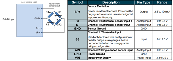
Measurement example: Full bridge load cell


V-Link-200
V-link-200 + WSDA-2000 or WSDA-200-USB

8 analog input channels. It includes onboard PGA, filtering, and high-resolution ADC for precise measurement of a large range of sensor types including strain gages, load cells, and pressure transducers. It has 4 differential analog channels and 4 single-ended analog channels.

TC-Link-200
TC-link-200 + WSDA-2000 or WSDA-200-USB

12-channel wireless sensor used for precise measurement of thermocouples and differential output sensors. There is no calibration required. Select the desired thermocouple type and the node will output accurate, low noise temperature or mV data.
Pinout and sensor wiring


CAN device setup for Dewesoft (MV5)
- Connect Dewesoft DSCAN2 device to USB port on computer and to MV5 in CAN0 port through MV5 special cable. Power is provided through a USB port.
- Start Dewesoft (license required unless using trial version)
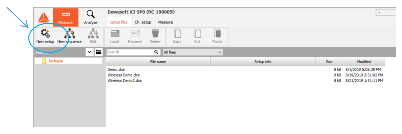
- Start new Setup
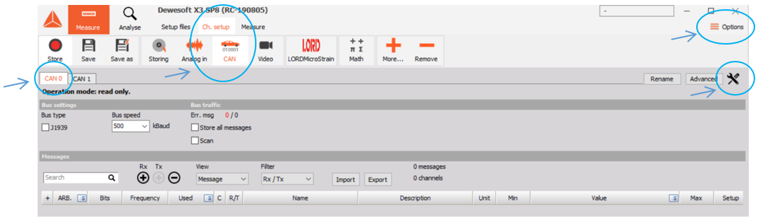
- The DSCAN2 device should be detected automatically. Once initiated, open the Settings menu for CAN0 to configure.
- Settings may automatically launch when software or new session is started
- Access through Ch. Setup > CAN > CAN0 > tool symbol
- Access through Options > Settings from any menu tab
- In Settings menu select Devices > Dewesoft Devices > DS-CAN2 > CAN0
- Operations mode = Read/write/acknowledge
- Default baud rate = any
- CAN plugin = None

- Close Settings and select Ch. Setup > CAN > CAN0
- Check Bus type = J1939
- Import the DBC file that designates MV5 channels from the CAN data stream
- MV5_v1.3.dbc (or newer version as available)
- Will be on MV5 product page on LORD website

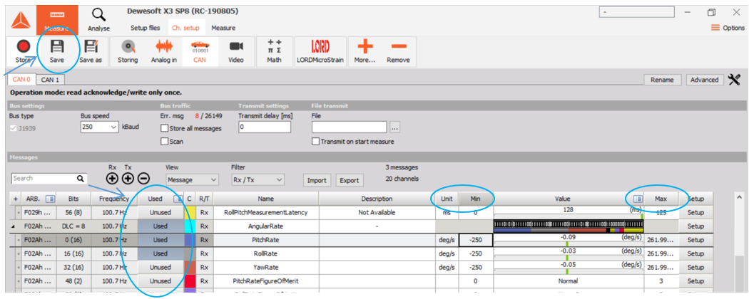
- Set up channels for data acquisition as needed
- Channel Min and Max to set the operational ranges
- Select Unused/Used button to enable and disable channels
- Other settings as needed
- Save channel setup
- Start data acquisition in Measure tab
- Design custom widget layouts in the Design menu
- Right-click on Custom or Recorder > Properties to name and save layouts
- Access on the Design menu bar and in the + More menu
- Click on the widget to assign channels from the right column
- Change widget settings in the left column
- Design custom widget layouts in the Design menu
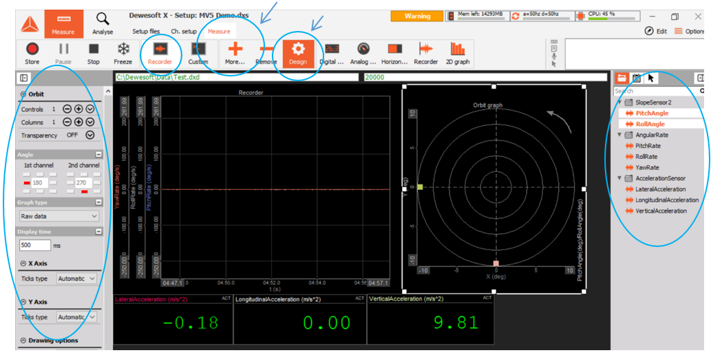
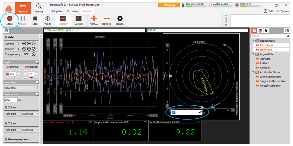
- Click on Design to exit the design space and start measuring
- Change axis ranges by clicking on the axis
- Data is only recorded if the Store button is used
Inertial sensors
The 3DM®-GX5-25 is the smallest and lightest precision industrial AHRS available. It features a fully calibrated and temperature compensated triaxial accelerometer, gyroscope, and magnetometer to achieve the optimum combination of measurement qualities under all dynamic conditions.
The inertial sensors are also supported in the Dewesoft LORD plugin. If the device is connected via USB select Add USB devices. If the device is connected via Serial interface, select the correct COM port and baud rate. After that select Add device.

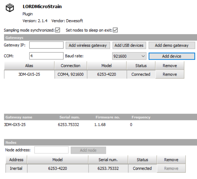
In the LORD setup you can select the sample rate and which channels you want to measure/store.
