Modbus on device
The Modbus module connects an embedded Dewesoft device to Modbus equipment. Configure a Server to expose device values to an external client, or a Client to exchange data with an external server. Both TCP/IP and serial RTU are available in the device interface.
This guide describes the device configuration shown in DewesoftX 2027.1. Screens show an OBSIDIAN-R12 selected as the configuration target. Available modules and signals depend on the device and its firmware.
1. Open Modbus on the device
- Select the measurement device in the left sidebar.
- Open Config.
- Select More… → Add module → Modbus under Aerospace and automotive.
- Open Modbus on the device toolbar.
Check the device name in the window title before adding the module. The on-device module belongs to the selected measurement device. The separate Modbus Client and Server extensions described elsewhere in the DewesoftX manual run in DewesoftX.
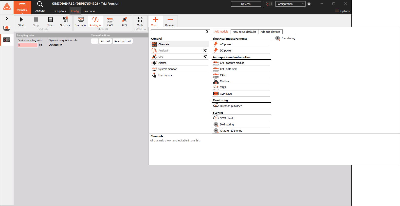
Figure 1. Device configuration with the Add module menu open.
Device modules execute as function blocks on the embedded system. See Modules embedded on DAQ devices for the general module workflow.
2. Module instances and endpoints
The upper tab, such as DSModbus_1, identifies the Modbus module instance. Its + tab adds another instance. The Used / Unused selector controls whether the instance is enabled.
Below the instance tab, use the round + button to add a Server or Client endpoint. Each endpoint has its own tab, such as Server_1 or Client_1, and its own connection settings and data records.
Select the endpoint tab before editing. The pencil button edits the endpoint name; the adjacent minus button removes the selected endpoint. Distinguish these endpoint controls from the separate plus and minus buttons in the Data area, which add and remove records.
3. Choose the communication role
| Role | Use it when | Connection behavior |
|---|---|---|
| Server | A PLC, SCADA system, or another Modbus client needs device values. | Listens for requests from clients. |
| Client | The device needs values from another Modbus server, or needs to send values to writable server locations. | Initiates requests to the configured server. |
The roles follow the same client/server distinction explained in Dewesoft’s Modbus Client and Modbus Server documentation. Use those pages for background and their linked extension manuals; use the controls in this guide for the embedded implementation.
4. Configure a TCP/IP server
Add a Server endpoint and select Protocol → TCP/IP.
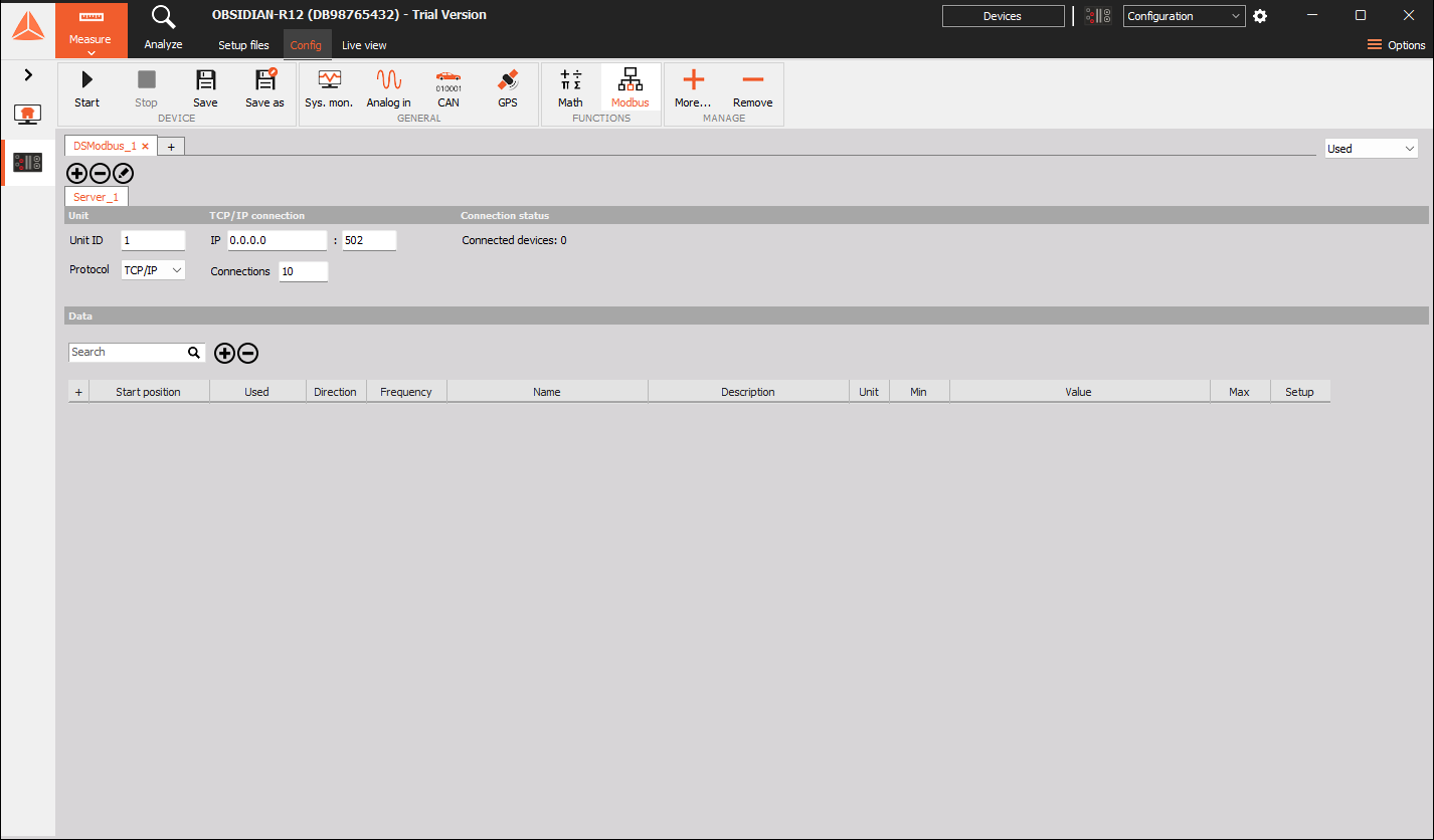
Figure 2. Server endpoint with Unit ID, listening address, port, connection limit, and connection count.
| Field | Function |
|---|---|
| Unit ID | Modbus unit identifier. Configure the requesting client to use the intended unit. |
| IP | Local listening address on the device. The initial value is 0.0.0.0, the wildcard listening address. |
| TCP port | Listening port. The initial value is 502. |
| Connections | Maximum configured number of client connections; initially 10. |
| Connection status | Shows Connected devices: n for the server endpoint. |
An external client must connect to the device’s reachable network address. Do not enter 0.0.0.0 as the remote destination in that client.
After configuring the connection, add the records and signals to expose. A listening server with no mapped records does not provide the required register map merely because a client connects.
5. Configure a TCP/IP client
Add a Client endpoint and select Protocol → TCP/IP.
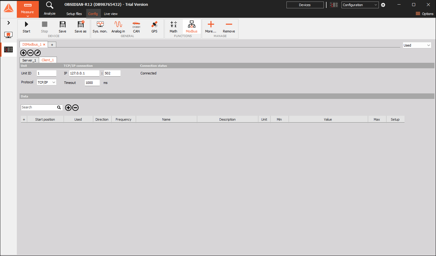
Figure 3. Client endpoint with remote IP, TCP port, Unit ID, timeout, and connection status.
| Field | Function |
|---|---|
| Unit ID | Unit identifier expected by the remote Modbus server. |
| IP | Address of the remote server. The initial value is 127.0.0.1. |
| TCP port | Remote server port; initially 502. |
| Timeout | Request timeout in milliseconds; initially 1000 ms. |
| Connection status | Shows the endpoint’s connection state, for example Disconnected or Connected. |
Replace 127.0.0.1 with the remote equipment’s address for an external connection. Loopback addresses refer to the system running the endpoint.
Configure the server’s actual table, address, data representation, and permitted direction when adding records. A Connected state confirms the connection state; check the mapped values separately.
6. Configure serial RTU
Select Protocol → RTU in the endpoint. The serial settings replace the TCP/IP fields.
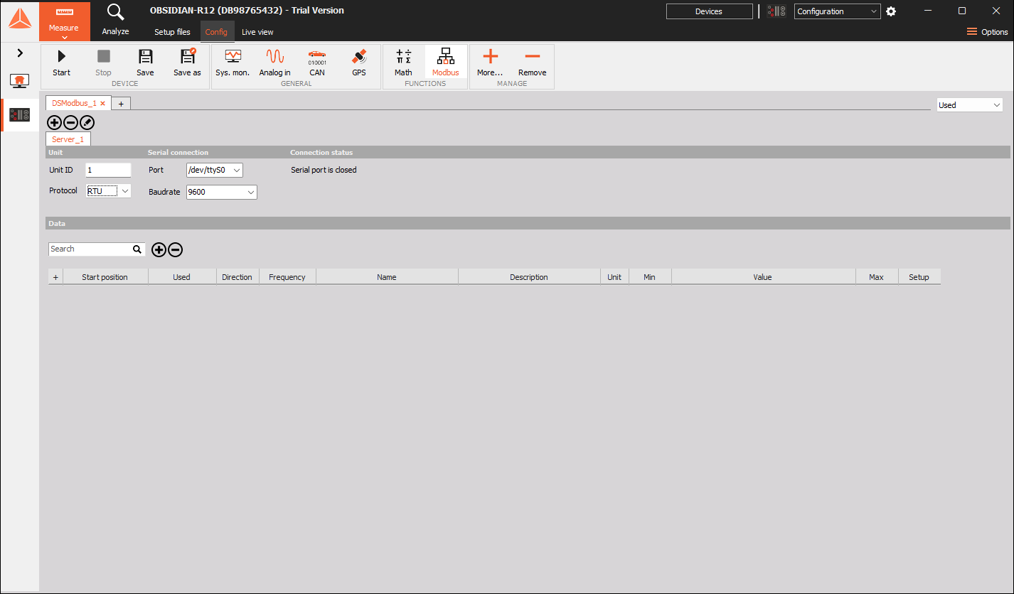
Figure 4. RTU server settings with a device serial port and baud rate.
| Field | Function |
|---|---|
| Unit ID | Modbus address for the intended unit on the serial network. |
| Port | Serial interface on the embedded device, such as /dev/ttyS0. |
| Baudrate | Serial communication speed. The list includes 9600, 19200, 38400, and 115200. |
Choose the port corresponding to the device’s physical serial interface and use the same communication speed as the other equipment. The Linux-style port names identify device interfaces, rather than Windows COM ports on the configuration PC.
Use the device hardware documentation for the connector, supported electrical interface, wiring, and termination. The Modbus connection panel shown here exposes Port and Baudrate; confirm any other required serial framing settings against the device’s supported configuration.
7. Add a Modbus data record
In the selected endpoint’s Data area:
- Select the round + button.
- Choose Discrete input, Coil, Input register, or Holding register.
- In Frame setup, enter Start position.
- Use the + button in the structure pane to add a signal.
- Select the signal in the tree and configure its representation.
- Select OK to return to the grid.
A record defines an addressed region of one Modbus table. Its child signals define the individual values or bit fields within that region.
Tables and addresses
| Record type | Modbus value | Conventional first reference | Standard read function |
|---|---|---|---|
| Coil | One bit; writable table | 00001 | 01 |
| Discrete input | One bit; read-only table | 10001 | 02 |
| Input register | 16-bit register; read-only table | 30001 | 04 |
| Holding register | 16-bit register; writable table | 40001 | 03 |
These are the standard Modbus table meanings. Supported operations also depend on the selected endpoint and the peer. See the Modbus Application Protocol specification for protocol addressing and function definitions.
Start position is the zero-based position within the chosen table. Address range displays the corresponding conventional reference range. For example:
- Holding register, Start position 0 → 40001.
- Input register, Start position 0 → 30001.
- Coil, Start position 0 → 00001.
Do not type 40001 into Start position to select the first holding register. Select the table first, then enter its offset. Configure the peer according to its own zero-based or reference-number display convention.
A value can occupy more than one register. Check Address range after changing the structure and avoid overlapping records within the same endpoint and table.
Receive and transmit
For client writable records, Direction offers Receive and Transmit. Receive reads values from the server; Transmit sends configured values to the server. Switching a client coil to Transmit exposes the input-source controls used to supply its outgoing value.
Read-only tables provide received data in the client. In the grid, RX identifies receiving, TX transmitting, and RX/TX a bidirectional signal.
The table’s writable classification does not mean every peer implements every write command. Match the peer’s supported operations and register permissions.
8. Configure signal representation
Select a child signal in the Frame setup structure tree.
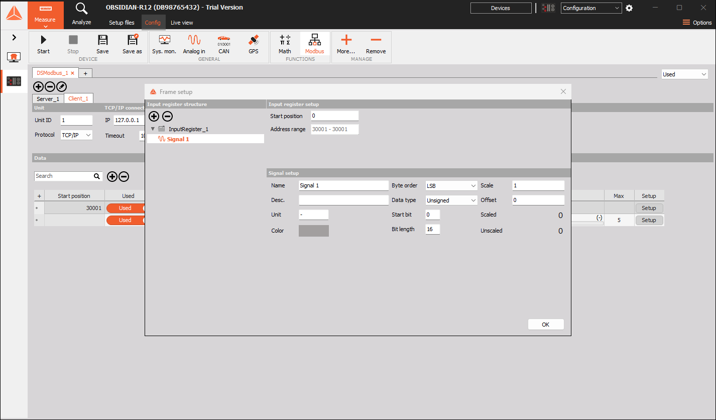
Figure 5. A received input-register signal with representation and scaling fields.
| Control | Function |
|---|---|
| Name / Desc. | Identify the signal and describe its meaning. |
| Unit | Engineering-unit label. |
| Color | Display color for the signal. |
| Byte order | Select LSB or MSB to match the data layout. |
| Data type | Select Unsigned, Signed, Float, or Boolean. |
| Start bit | Position of the signal within the record. |
| Bit length | Width of the signal. |
| Scale / Offset | Conversion settings for the signal. |
| Scaled / Unscaled | Numeric previews that help compare the converted and raw representations. |
A new register signal initially uses Unsigned, Start bit = 0, and Bit length = 16. A new coil signal initially uses Boolean and Bit length = 1.
Use the remote equipment’s register map to choose signedness, width, scaling, and byte order. For example, a 16-bit integer and a floating-point value require different interpretations even when they begin at the same address. Confirm multi-register layouts with a known value before using them in a measurement.
For received engineering values, use the register map’s scaling convention. A common conversion is engineering value = raw value × scale + offset. Check the displayed Scaled and Unscaled previews and a known peer value to confirm the selected conversion, especially for outgoing data.
Adding a unit label does not itself convert a number.
9. Supply server or transmitted values
Server signal configuration and client Transmit configuration provide an Input selector.
Constant
Select Input → Constant and enter Value to provide a fixed numeric value.
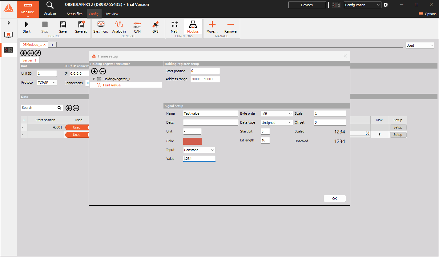
Figure 6. A 16-bit unsigned holding-register signal at Start position 0, with constant value 1234.
A constant is useful when commissioning the connection: the peer should recover the known value using the same table, address, width, and byte order. After the mapping is correct, replace the constant with the intended source.
Raw hex
Select Input → Raw hex to enter a hexadecimal value. This is useful for checking an exact bit pattern against the peer’s interpretation.
Signal
Select Input → Signal, then choose a device signal from the Signal list.
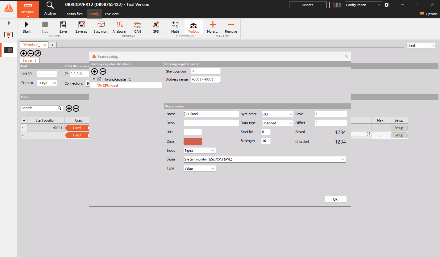
Figure 7. A holding-register signal assigned to System monitor 1/Sig/CPU (AVE), with Type set to Value.
The list contains available signals on the selected device. Configure a measurement channel or function-block output in its source module first if it is missing.
Type offers Value, Evaluation, and Range evaluation. Use Value for a direct source-value mapping. Evaluation modes provide alternative source handling; confirm the required evaluation behavior in the device’s applicable function-block documentation before depending on it for a threshold or alarm.
For a changing quantity, select a representation with sufficient range and precision. Match it in the receiving client.
Counter
Select Input → Counter to expose counter-related input settings, including Min and Max.
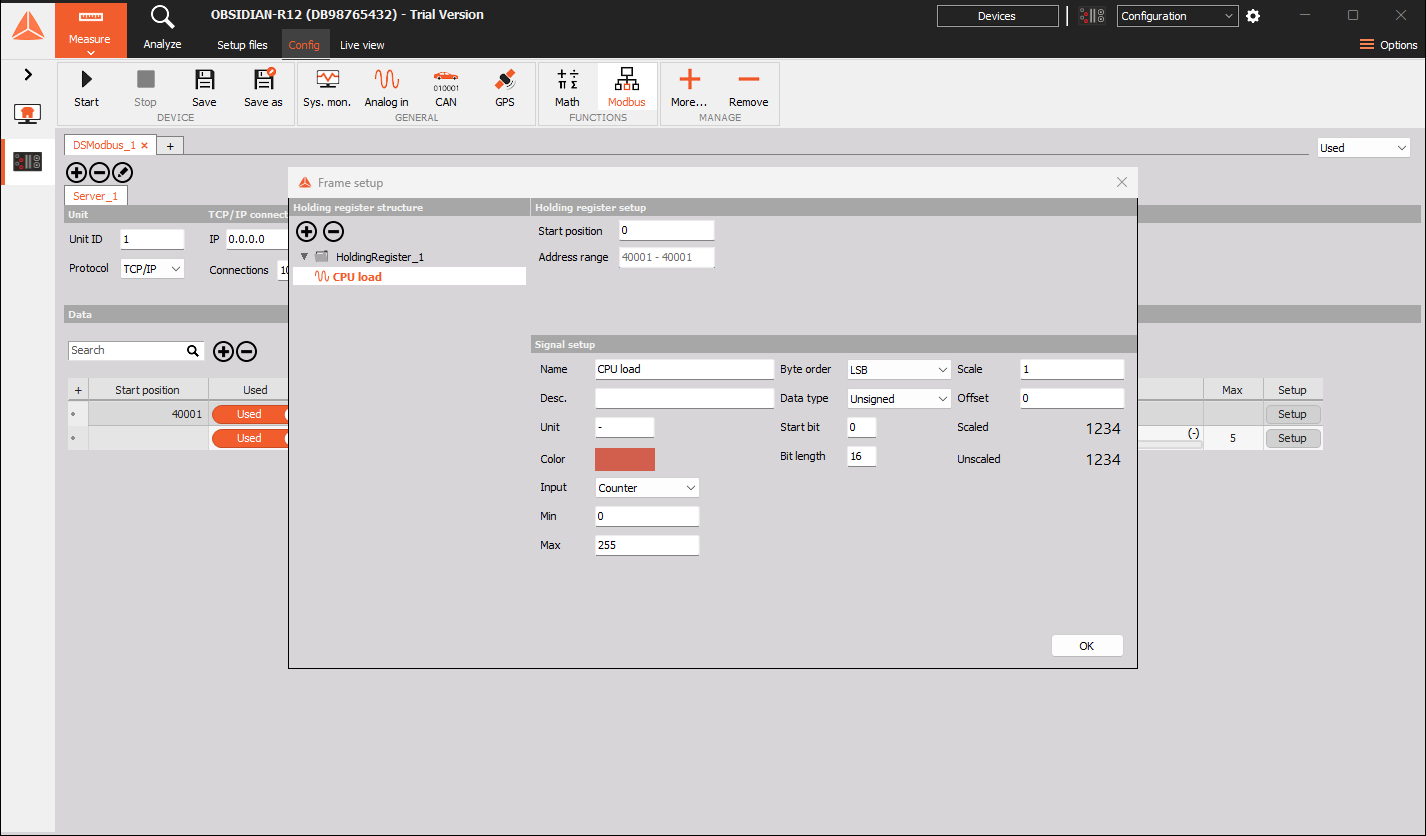
Figure 8. Counter input selection and its range controls.
Use a counter source when the peer needs a changing test or sequence value. Set limits compatible with the selected data type. Confirm the update cadence and rollover behavior required by the receiving application.
10. Review and maintain the data grid
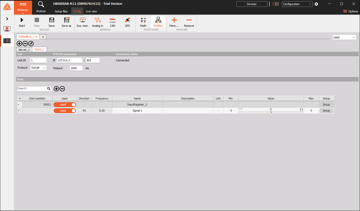
Figure 9. Client input-register record and its child signal. Connection state and mapped data must be checked separately.
| Column or control | Function |
|---|---|
| + at the left | Expand or collapse a record’s child signals. |
| Start position | Displays the record’s conventional Modbus reference. |
| Used | Enables or disables a record or signal. |
| Direction | Shows RX, TX, or RX/TX. |
| Frequency | Shows the signal frequency. |
| Name / Description | Identify the record or signal. |
| Unit | Signal’s unit label. |
| Min / Max | Configured signal display range. |
| Value | Current displayed value. |
| Setup | Reopens the record or signal configuration. |
| Search | Filters the grid to help find records and signals. |
| Data-area minus | Removes the selected record. |
Check both the parent record and required child signals are Used. Clear Search if an expected record is absent. Min and Max describe the configured range; they are not measured extrema.
For an overview of device signals and naming, see Channels.
11. Commission a connection
Publish one device value
- Add a Server endpoint and configure its TCP/IP listening settings or RTU interface.
- Add a Holding register at Start position 0.
- Add a 16-bit Unsigned signal with Start bit 0, Scale 1, and Offset 0.
- Choose Constant and enter 1234.
- Configure the external client for the same Unit ID, holding-register table, and zero-based address 0.
- Read one register and verify 1234 at the client.
- Change the constant deliberately and confirm that the client follows it.
- Replace the constant with the required device Signal and verify its range and precision.
Read a remote measurement
- Add a Client endpoint and enter the remote server’s connection settings.
- Read the equipment’s register map to identify the table and offset.
- Add the corresponding record and a child signal.
- For a writable table used for reading, select Receive.
- Match bit position, width, data type, byte order, and scaling to the equipment.
- Enable the record and signal, then check connection state and Value.
- Compare a deliberate source change with the value received by the device.
Use the device’s Start and Stop controls when changing its operating state is required. Retain the intended configuration using the device’s Save or Save as controls, then verify the configuration used after reconnecting or restarting the device.
12. Display and record Modbus signals
Received Modbus signals can be selected for device processing or display where they are offered in the channel list. Open Live view and assign the required channel to an appropriate widget. A numeric display shows the current value; a recorder helps reveal changes.
Modbus mapping and measurement recording are separate configurations. To record values on the device, select the required signals in the appropriate storing module and check the recorded file. See On-device storing.
13. Troubleshooting
| Symptom | Check |
|---|---|
| Modbus is missing | Select the intended embedded device and inspect Config → More…. Check device/firmware support. |
| Client stays Disconnected | Remote IP, port, Unit ID, server availability, timeout, and network route from the device. |
| Server shows zero connected devices | Confirm a client is connecting to the actual device address and listening port. |
| TCP works from the PC but not from the device | Check the device’s own network route and the server’s access rules. |
| RTU does not communicate | Device serial port, wiring, electrical interface, baud rate, unit address, and required serial framing. |
| Connected but the value is zero or unchanged | Table, offset, Used states, direction, available source data, and peer register permissions. Connection alone does not establish correct data. |
| Illegal-address response | Wrong table, off-by-one addressing, unmapped region, or a request extending beyond the defined range. |
| Wrong sign or magnitude | Data type, bit length, byte order, Scale, and Offset. |
| Integer looks correct but a wider value does not | Multi-register ordering and signal width on both ends. |
| Transmit source controls are missing | Select a writable client table and set Direction to Transmit, or configure a server signal. |
| Signal is absent from the source list | Enable/configure it in its source module on the selected device. |
| Value is visible but absent from a recording | Select it in the storing module and verify the recorded file. |
Related manuals
- Modules embedded on DAQ devices — adding embedded function blocks.
- Modbus Client — DewesoftX extension and linked TCP/IP client manual.
- Modbus Server — DewesoftX extension and linked TCP/IP server manual.
- Channels — device signal overview and naming.
- On-device storing — recording device signals.