Kinematic marker
For more information about kinematic marker, please visit Processing markers page.
Kinematic markers are used to identify the bearing frequencies and bearing faults.
To use the Kinematic marker we have to add the Envelope detection math channel.
Each bearing database includes bearing data (what is the base of the component (cage, rolling element, outer race, and inner race) at 1 Hz and at which frequency has the component a peak in the frequency domain).
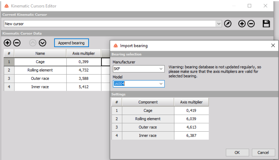
To add a new bearing go to the Kinematic cursor editor.
In the Kinematic cursor editor, add a new bearing or select from the existing database, selecting the Append bearing option.
Channel calculated with Envelope detection math must be now set as the input channel to the FFT analyzer.
At the measurement screen of the FFT analyzer, right click and select adding Kinematic marker.
- Current value - shows only a current value of the marker and can be interacted while storing
- Full history - stores calculated values in output channels and can be used as input in other modules
- Snap to data points - if this option is selected, the position of the marker will be snapped to the FFT bin, otherwise the marker can be placed at any frequency with the value being interpolated at that exact frequency
- Find peak in region - if this option is selected, the marker will automatically search for the peak in the selected frequency band centered on the position of the marker
- Improve peak accuracy - if this option is selected the peak position and value are interpolated from the FFT data
- Kinematic cursor - assign the appropriate marker from Kinematic cursor editor
- Position source - the position source has two modes - Widget marker andChannel. If widget marker is selected, the position of the marker is defined manually. If Channel mode is selected, the position of the marker is defined by the current value of our chosen channel.
- Frequency of rotation - frequency of rotation determines the position of the kinematic markers. The frequency must be imputed manually and can be defined in Hz or RPM.
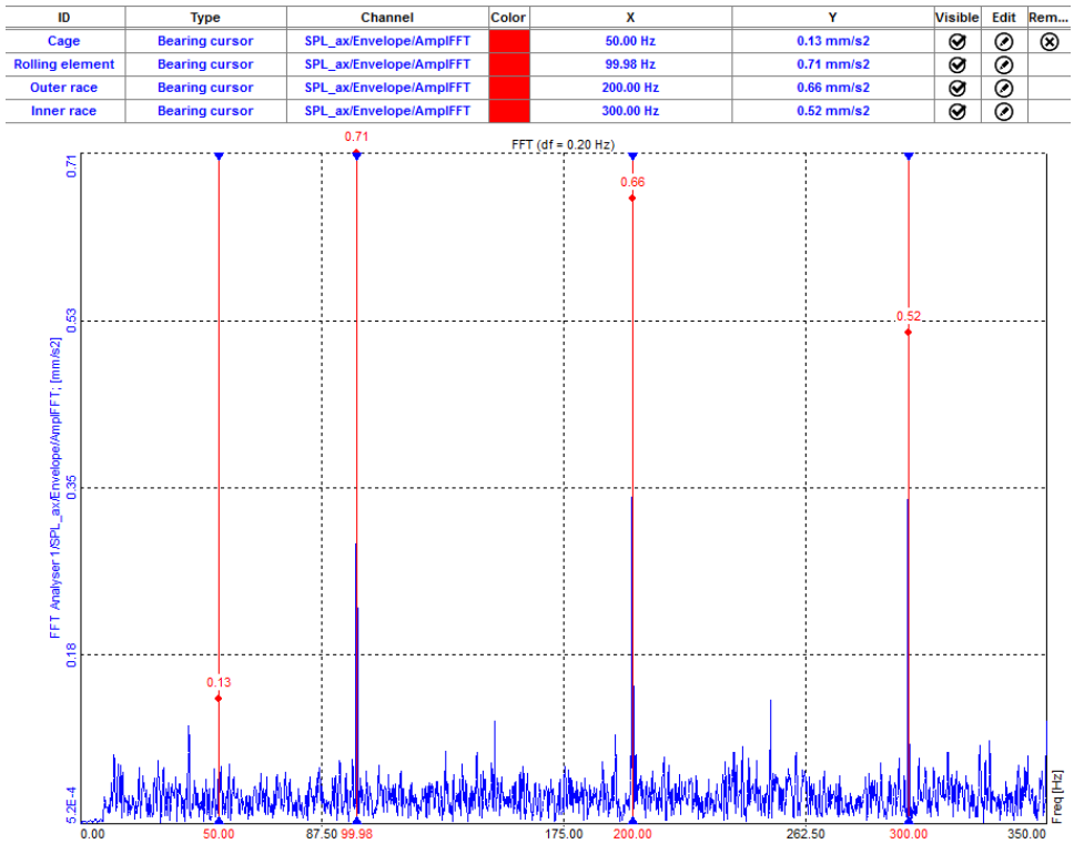
Now we can see kinematic markers at frequencies that are defined in the kinematic cursor database. The table shows to which mechanical part the frequency is related.
Kinematic markers are also visible on the 3D graph.