Strain Rosette
Use Strain rosette to combine readings from a strain-gauge rosette and calculate the principal strains, their direction, and the resulting stresses.
A gauge measures strain along its own axis. The module combines the gauges to find the directions of greatest and least normal strain in the measured surface.
Set up a rosette
- Select your device and open Config → Math.
- Select Add math → Strain, stress → Strain rosette.
- Choose the rosette Type to match the physical gauge arrangement.
- Assign the strain channels to StrainA, StrainB, and, where required, StrainC. Match A, B, and C to the drawing in the setup.
- Set the input and output units. Enter the material’s Young modulus and Poisson ratio if you need stress results.
- Select the required results under Output signals and click OK.
The inputs must already represent strain and have the same sampling rate. Configure the strain-gauge measurement and scaling in the input channels first. Raw voltage or bridge readings must be converted to strain before using them here.
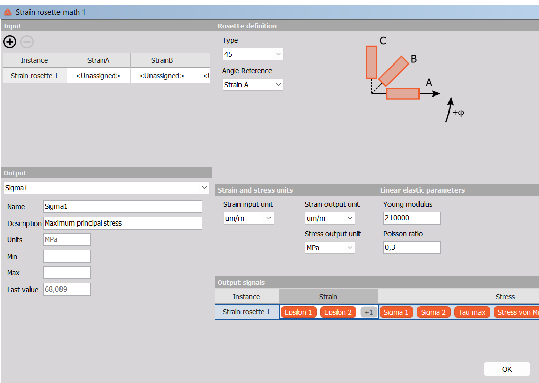
45° configuration before assigning the strain channels. The screenshot illustrates the setup controls; a retained Last value is not a current result while inputs are unassigned.
Choose the gauge arrangement
| Type | Gauge directions relative to A | Required inputs |
|---|---|---|
| 45° | A: 0°, B: 45°, C: 90° | A, B, C |
| 60° | A: 0°, B: 60°, C: 120° | A, B, C |
| 120° | A: 0°, B: 120°, C: 240° | A, B, C |
| 90° | A: 0°, B: 90° | A, B |
Use the module’s drawing and the gauge manufacturer’s markings to identify the channels. Swapping B and C can change the calculated direction.
The 90° type assumes that the two gauges are already aligned with the principal strain directions. Two perpendicular gauges cannot determine an unknown shear strain or find arbitrary principal directions.
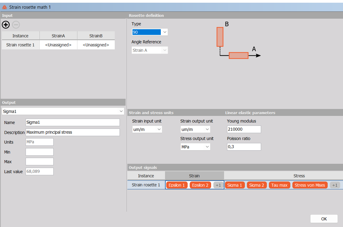
Selecting 90° removes StrainC. In the inspected version, Angle Reference is fixed to Strain A.
Set the units and material
- Strain input unit: select the unit of the values supplied by all input channels.
- Strain output unit: select the unit for Epsilon1 and Epsilon2.
- Stress output unit: choose MPa, psi, or KSI.
The strain choices um/m and ue both represent microstrain. A value of 1000 microstrain equals 0.001 m/m. Selecting m/m for values that are actually in microstrain makes the interpreted strain one million times too large.
Young modulus describes the material’s stiffness. In the inspected device build, enter it in MPa (N/mm²): for example, 210000 MPa equals 210 GPa. Poisson ratio is dimensionless; enter the value for the test material. The displayed 210000 and 0.3 are examples, not settings for every material.
The material settings affect stress results. They do not change the principal strains calculated from the gauge readings.
Understand the results
| Output | Meaning |
|---|---|
| Epsilon1 | Maximum principal normal strain in the plane. |
| Epsilon2 | Minimum principal normal strain in the plane. |
| Angle | Direction of Epsilon1 relative to the selected reference gauge, in degrees. |
| Sigma1 | Maximum principal normal stress in the plane. |
| Sigma2 | Minimum principal normal stress in the plane. |
| Taumax | Maximum shear stress in the measured plane. |
| StressVonMises | Nonnegative equivalent stress for the plane-stress state. |
| StressVonMisesSigned | Same magnitude as von Mises stress, made negative when $|\sigma_2|>|\sigma_1|$. |
For three-gauge rosettes, Angle Reference selects the gauge used as the angular reference. Changing it changes the reported angle, not the principal strain or stress magnitudes. Gauge axes repeat every 180°, so directions differing by 180° describe the same principal axis. When the two principal strains are equal, there is no unique principal direction.
The Output selector lets you inspect a result and edit its name and description. The device version provides the eight outputs listed above.
How the strains are calculated
Let $\varepsilon_A$, $\varepsilon_B$, and $\varepsilon_C$ be the gauge strains in one consistent unit.
The module finds the centre $C$ and radius $R$ of the strain Mohr’s circle. The principal strains are:
$$ \varepsilon_1=C+R,\qquad \varepsilon_2=C-R $$
Here $C$ is the average of the two principal strains. $R$ describes their separation; twice the radius is the maximum engineering shear strain in the plane. $C$ and $R$ are calculation quantities, not additional outputs in this device version.
45° rosette
$$ C=\frac{\varepsilon_A+\varepsilon_C}{2} $$
$$ R=\frac{1}{\sqrt{2}}\sqrt{(\varepsilon_A-\varepsilon_B)^2+(\varepsilon_B-\varepsilon_C)^2} $$
With Strain A as the angle reference:
$$ \theta=\frac{1}{2}\mathrm{atan2}\left(2\varepsilon_B-\varepsilon_A-\varepsilon_C,\ \varepsilon_A-\varepsilon_C\right) $$
The atan2 function selects the correct quadrant. Its result is halved because Mohr’s-circle angles are twice the physical angle. Convert radians to degrees for the Angle output.
60° and 120° rosettes
Both arrangements use:
$$ C=\frac{\varepsilon_A+\varepsilon_B+\varepsilon_C}{3} $$
$$ R=\frac{\sqrt{2}}{3}\sqrt{(\varepsilon_A-\varepsilon_B)^2+(\varepsilon_B-\varepsilon_C)^2+(\varepsilon_A-\varepsilon_C)^2} $$
With Strain A as the reference, the 60° angle is:
$$ \theta_{60}=\frac{1}{2}\mathrm{atan2}\left(\sqrt{3}(\varepsilon_B-\varepsilon_C),\ 2\varepsilon_A-\varepsilon_B-\varepsilon_C\right) $$
For 120°, the numerator changes sign:
$$ \theta_{120}=\frac{1}{2}\mathrm{atan2}\left(\sqrt{3}(\varepsilon_C-\varepsilon_B),\ 2\varepsilon_A-\varepsilon_B-\varepsilon_C\right) $$
This is why the gauge order matters even when the principal strain magnitudes are unchanged.
90° rosette
The module takes the larger of A and B as Epsilon1 and the smaller as Epsilon2. Relative to A, Angle is 0° when A is greater than or equal to B, and 90° otherwise. This calculation relies on the principal-direction assumption described above.
How stresses are calculated
Stress results assume an isotropic, linear-elastic material under plane stress. The stress perpendicular to the measurement surface is assumed negligible.
First express strain as dimensionless m/m. If the inputs are in microstrain, multiply them by $10^{-6}$. Using Young’s modulus $E$ and Poisson’s ratio $\nu$:
$$ \sigma_1=\frac{E}{1-\nu^2}(\varepsilon_1+\nu\varepsilon_2) $$
$$ \sigma_2=\frac{E}{1-\nu^2}(\varepsilon_2+\nu\varepsilon_1) $$
These equations include the influence of both principal strains. Applying $\sigma=E\varepsilon$ separately to each gauge does not give the general biaxial stress state.
The remaining stress results are:
$$ \tau_{\max}=\frac{\sigma_1-\sigma_2}{2} $$
$$ \sigma_{\mathrm{vM}}=\sqrt{\sigma_1^2-\sigma_1\sigma_2+\sigma_2^2} $$
Taumax is the maximum shear in the plane. It is not necessarily the absolute maximum shear in three dimensions, which also considers the out-of-plane principal stress of zero.