ARINC 429 and MIL-STD-1553 Plugin
MIL-STD-1553 is a standard defining a local area network (LAN) originally developed for and widely used on military aircraft with ARINC 429 being similar in commercial settings. This digital, command response, time-division multiplexing network protocol is also used in many other military and commercial applications. The standard defines the handshaking, data formats, and timing requirements of the protocol as well as the electrical characteristics of the bus and the terminals’ interface electronics.
The Dewesoft 1553 plugin can take in 1553 and 429 communications protocols allowing the user to interface with existing busses of communication for data collection purposes. Being able to interface with these protocols allows you to send Dewesoft information that can be centralized with other collected information within the Dewesoft software.
NOTE: The use of external conversion devices may be required such as ALTA DT or Ballard boxes. This will be discussed in later sections.
NOTE: Through the manual 1553, 429 and ARINC will be used interchangeably. Note that they are ref the same.
Recent changes (as of version 3.2.3)
All recent changes have been bug fixes and corrections. No new features have been added in 2020.
Required Software
Dewesoft 1553 License (obtainable from your Dewesoft point of contact) Dewesoft Professional software .DLLs will be required from versions of external conversion hardware. This requirement will be discussed within the respected sections.
Enabling 1553 Plugin
To use this additional plugin, we will need to install it within the Dewesoft software by performing the following steps (current as of X2021.2):
1) Open Options (top right corner)
2) Click Settings
3) New dialog box will appear.
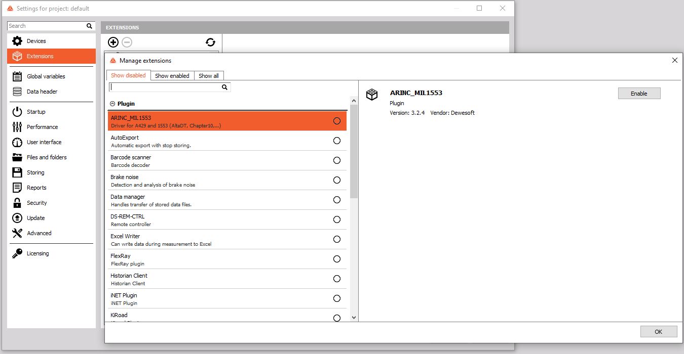
4) Clicking on the “Extensions” on the left side will allow you to press the “+” button creating a new dialog box with a list of Extensions.
In which the 1553 will be an option.
5) Check the box on the right side and then hit OK, then OK.
Initial Setup
Within the project settings (Options, settings menu)
After the extension is loaded. There will be under plugin, 1553. Click on that to open the settings for the 1553 interface
Four (4) sources will be available to choose from:
1) AltaDT
2) Chapter 10
3) Ballard
4) Replay
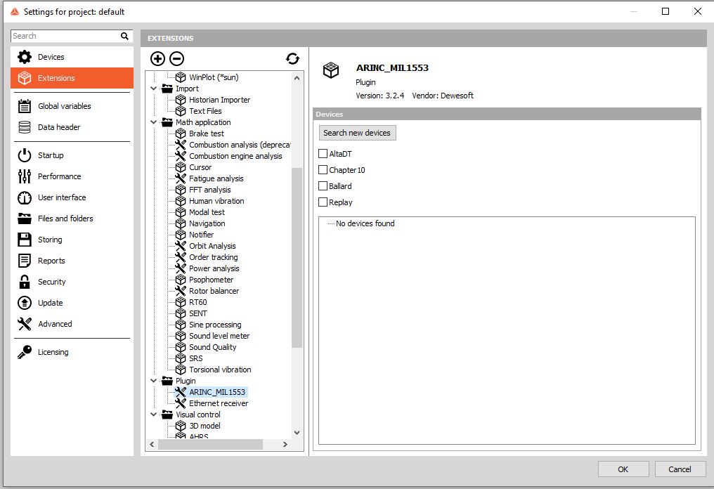
Select the interface that is used to feed the 1553 plugin with information from your setup.
Once the selection is made, further options will become available to help setup the required information for interface
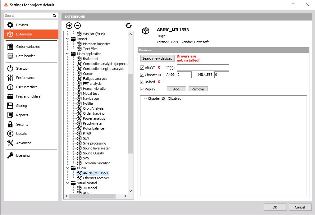
“Search new devices” is an option on the top and can be used to quickly interface with installed inputs.
If drivers are missing, a RED warning will become apparent saying the error that is required to be corrected prior to moving forward with the linking,
A status box below will populate with information relevant to setup informing you of errors, status or any information that is required.
Conclusion: Once communication is established, you can confidently close this setup area and proceed back to Ch. Setup tab within DS to start working with the interface in the same way you would other protocols such as analog in channels.
Initial setup of the Alta DT interface
Manuals for the proper Alta DT are available on the manufacturers website and contained within this section is extracted information that will help with the interface.
Two .DLL files are available from Alta DT and Dewesoft that are required for initial setup. These can be loaded within the proper section of the Dewesoft software location.
NOTE: Add ADT_L0.dll and ADT_L1.dll (not ADT_L0.lib)
The IPv4 address by default is: 192.168.0.128 Users can change this value by reprogramed/ flashed as needed.
It is recommended that all communications be closed down on the windows settings. Leaving only the Alta DT as the only communications device with a STATIC IP address.
All Alta DTs use the same starting three MAC address naming: 94:9C:55….. for ease of hardware location.
USB power source: It is recommended a >1000mA source is used. A low grade wall power source will not have enough to meet Alta DT power requirements for external devices.
AltaView is a program that is required to be installed separate from Dewesoft that will allow control of the Alta DT hardware and initial setup requirements
NOTE: It is critical that AltaView be closed and not running in the background prior to opening Dewesoft.
Initial setup of the Chapter 10
Using recorded chp 10 files, you can play them back through this plugin allowing the 1553 and 429 protocols to be seen and used similar to that of any other channels. The importation and control of them will come from this plugin with the chp 10 as the source
NOTE: Chp 10 plugin is required for use with this plugin and may not be included with some packing. Please ensure proper chp 10 plugin operation prior to using together to avoid unnecessary errors.
While under the project settings, extensions, 1553, with the radio box checked for Chapter 10. The software is requesting “how many busses are on each communication?” The number that you enter is the amount of busses for each 1553 and 429 that are contained within the Chp 10 file that you wish to interact with. Enter the proper number, hit OK and then proceed to the Ch. Setup tab within the software.
Initial setup of the Ballard
Manuals for the proper Ballard interface are available on the manufacturers website and contained within this section is extracted information that will help with the interface.
Drivers for the Ballard interface are included with the interface provided and are required to be installed properly prior to incorporation with Dewesoft.
Initial settings of the Ballard interfaces are available from Ballard customer support section directly. Obtaining the proper API must be done through them.
Initial setup of the Replay
Within Project settings- Extensions, the ability to replay of ARINC/ 1553 is possible and can be loaded within this section
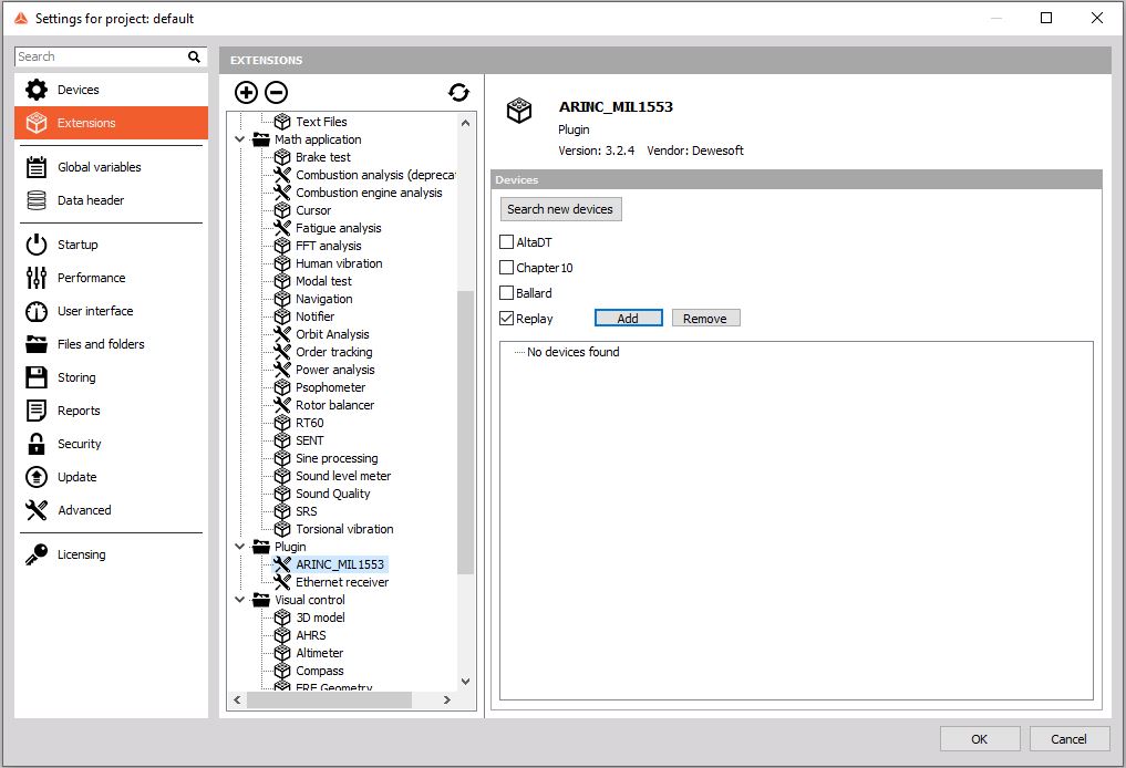
Once ‘Add’ is selected, a dialog box will appear to select the proper file to replay within the settings.
Dewesoft Channel setup
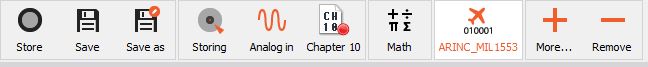
Now that communications with the proper gateway has been established. You will notice on the Toolbar a new 1553 icon
All of your interfacing with 1553 can be done here and appears similar to this: Busses will appear in each tab.
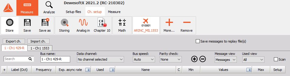
Stepping through functionalities and buttons: Import and Export: This will allow an external “Bus setup file” to be imported or exported through this reducing setup time and creating redundancy. While it may be possible to import an old file, new file creations within DS software will always export and import between DS platforms.
Save messages to replay files: This radio button when clicked, allows you to store the messages on the bus to an external file for record keeping. Click the box to enable this recording feature. Default is unchecked at all times.
Tabs: If you will notice that the tabs are setup as individual busses of the communications separating them and allowing ease of management between communication busses.
429 Busses (working left to right)
SEARCH box allows the user quick searches of the entire loaded data file for ease of location within the list. Simply type and locate.
Bus Name- User can name this bus to whatever they would like
Data Channel- this drop down allows channel selection
Bus Speed- 3 options are available Slow, Fast, Auto. Auto is on by default and may need adjustment from the user to match the external interfaces ensuring that the software is looking for the proper speed of the interfaces bus output.
Parity check- Three options are available- None, even, odd. Use this feature if a parity check is required selecting the proper function. None is set by default.
The** “+” and “-“** allows the user to add the required channels manually with a separate dialog box that will appear. In that dialog box, you can map the information that is required INSERT PIC HERE.
Message View: This has two options from a dropdown, Message or channel view. You can view the dialogs as messages or as channels. Default is set to Messages.
Used view: All or Used. After establishing the list of parameters from the bus, you can use and unuse channels similar to that of an analog channel. This allows the user to select the view of just used channels making the scrolling or driving of information faster. Default is set to All unless changed by user.
Scan: this radio box allows the program to scan the bus for you. Default is unchecked and when checked, the software will scan that bus ensuring no loss in information.
Measurement
If the data channel is set to “Used” within the setup screen, we can now switch to the Measure mode.
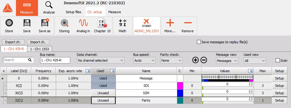
Channels that are used in the setup screen are now usable similar to other channels such as analog inputs. The 1553/ 429 channels set to used are now available on the right-side area under the header in measurement mode. They will be under folders which may require the use to select the down carrot and then open the tab, then data that is required. The carrots exist to expand and collapse high channel counts of parameters.
FAQ
This section should help to find quick solutions for common problems.
Problem: Data is not moving into DS via an Alta DT interface
Solution: Ensure that Alta DT software is not open prior to opening Dewesoft software. AltaView can be used as a troubleshooting tool before opening Dewesoft software to ensure a flow of data. Ensure that you go into task manager prior to opening Dewesoft software and close any Alta DT operations.
Problem: 1553/ 429 Channels are not present within the Measurement screen
Solution: Ensure the channel is “used” within the ch. setup screen, ethernet receiver plugin, and under the appropriate feeds.
Version History
Version history is retained by DEWESoft and is accessible via software changelogs to include module change history and documentation version.