Counter sensors
Dewesoft offers counter sensor database which holds the list and the properties of the counter sensors which can be used in order tracking, combustion analysis, and angle sensor math. We can define encoders, Geartooth, and other angle sensors.
For configuring Counter math calculations please see the Counter Math page.
The Counter sensor editor can be accessed under Settings - Counter sensor editor.
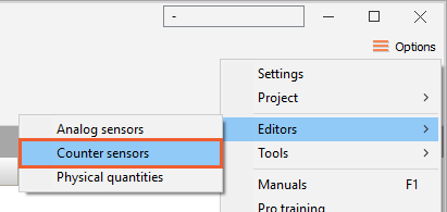
When we enter the editor, the following window appears where we define the counter sensors:
Several predefined sensors are already in the editor list; these sensors are installed with Dewesoft. We can always add new ones, modify existing ones or delete the sensors. On the upper right side of the Counter sensor editor, the window common command icons appear:
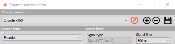
Rename sensor - rename the default or pre-defined sensor.
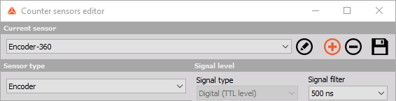
Add sensor - button will add a new sensor. The sensor will be named ‘New sensor’, but we can rename it.
Remove sensor - button will remove the currently selected sensor.
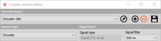
Save and exit - button will save the counter sensor database and close the editor.
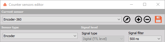
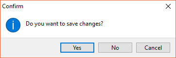
Exit - button will leave the editor without saving the data, so please be sure to use Save & Exit if you make any changes to the sensors or confirm you want to save the changes when you exit the editor.
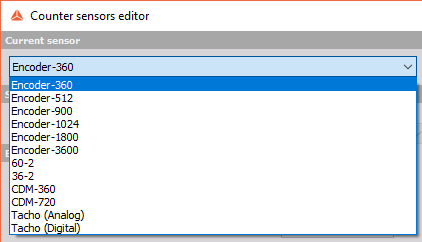
In the counter sensor editor window, we can choose any sensor from the current sensor drop-down list for viewing and editing.
Settings and entered values for Counter sensor are divided into following sections:
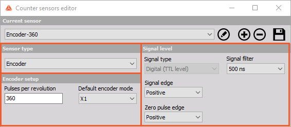
- Sensor type
- Signal level
- Encoder setup or Geartooth setup (depend on selected sensor type)
Counter Sensor Type
There are several basic sensor types available which can be selected from the Sensor type drop-down list:
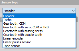
- Encoder - Classic angle encoder with A, B and Z signals. The signal can be only digital.
- Tacho - Sensor with one pulse per revolution. The signal can be either analog or digital.
- Geartooth, CDM - Sensor with the defined number of pulses per revolution, but without any zero pulses.
- Geartooth with zero, CDM + TRG - Sensor with the defined number of pulses per revolution with zero pulses.
- Geartooth with missing teeth - A classic in-vehicle sensor with any number of pulses where one tooth is missing for zero pulse recognition. A typical example is 36+1 sensor.
- Geartooth with double teeth - An in-vehicle sensor with any number of pulses per revolution with some double teeth missing. A typical example is the Geartooth with 60 teeth where two of them are missing, so in fact, there are 58 teeth and there is a gap between two teeth.
- Linear encoder - Sensor measuring displacement with any number of pulses per millimeter and pulses per revolution.
- Linear pulses sensor - A linear sensor, measuring displacement with any number of pulses per millimeter.
- Tape sensor - An angle sensor with white tape and black stripes attached to the rotating disc.
Counter Signal Level
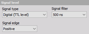
There are several signal level settings. From the drop-down list it can be selected:
Signal Type
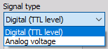
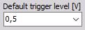
The encoder and Geartooth signal type can be only defined as digital (TTL level) and therefore used with counters while all other sensors can be also analog, which means that we need to define the trigger level.
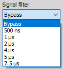
Signal Filter
The signal filter is a debounce filter, used to prevent glitches in the signal. A signal must be present for the defined amount of time before the logis accepts it as a valid signal. This also inserts a delay for the signals!
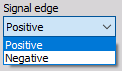
Signal Edge
Signal edge can be either positive or negative.
Encoder Setup
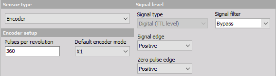
To prepare the encoder for the measurement, we have to define:
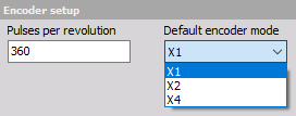
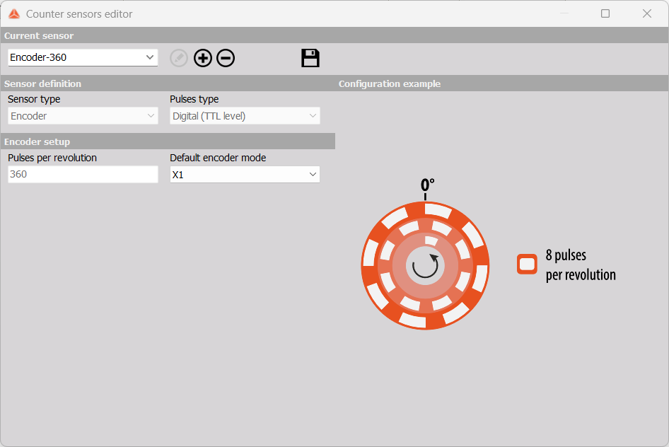
- Number of pulses per revolution - Standard values are multiples of 2 (256, 512,1024). These sensors are mainly used for external clocking so that we can have the frequency spectrum as a direct multiple of the number of revolutions to easily see the harmonic components. Other standard values are related to degrees (360, 720, 1800, 3600) where the reason is a nice angle resolution.
- Default encoder modes - Exact description of encoder modes can be found in the Dewesoft PRO training.
For additional help with visit Dewesoft PRO training ->Dewesoft Web page -> PRO Training -> Counters.
Tape Sensor Setup
Tape Sensor Settings
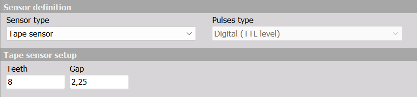
Tape sensors are angle sensors which detect reflected pulses on white reflecting tape having black stripes on rotating discs or shafts.
The zero position is defined by the long black gap, where white stripes are missing. Since the circumference of the disk is not exactly a multiple of the stripe width, the size of the long gap is not an integer, but can have a non-integer size (defined relative to the tooth size).
One tooth in this context is the width of adjacent white and black stripe pairs, which together produce a pulse, which is detected by the counter input.
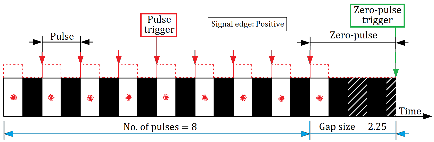
The following example shows a zebra tape with 9 white stripes and a gap.
Dewesoft definition
The number of teeth of a tape sensor based on the Dewesoft definition is the number of regular sized pairs of white and black stripes.
In the picture example above, the number of teeth is 8, because there is 8 regular sized white and black stripe pairs. The number of teeth can also be determined by counting the number of white stripes minus one used for the gap, here 9 -1 = 8.
The gap size in Dewesoft definition is the width of the last pair of white and black stripes expressed relative to the regular tooth size. In this example, the gap size is 2.25. Consider the hatched areas in the last black stripe on the picture above, which show the missing white stripes, to see why this is the case.
For the tape sensor definition this is expressed as below:
Geartooth Sensor Setup
Geartooth Sensor Settings
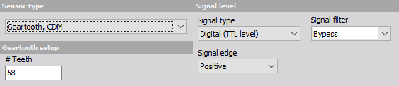
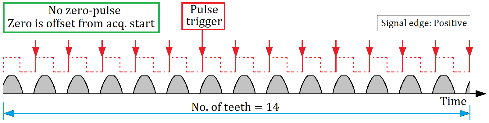
For these sensors, we need to define the number of pulses per revolution (number of teeth). In the picture below the geartooth sensor is set to 58 pulses på revolution.
How gears are genereting pulse triggers are sketched in the drawing below for another gear which has 14 teeth:
Geartooth with zero sensor settings
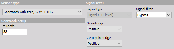
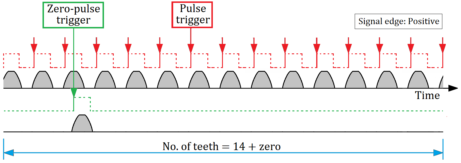
For these sensors, we need to define the number of pulses per revolution (number of teeth) and the direction of the zero pulse edge. In the picture below the geartooth sensor is set to 58 pulses på revolution and the Zero pulse edge set Positive:
How gears that include a zero pulse signal are genereting pulse triggers and zero-pulse triggers are sketched in the drawing below, for a gear which has 14 teeth and 1 keyphasor zero-pulse tooth:
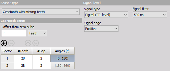
Geartooth with missing teeth sensor settings
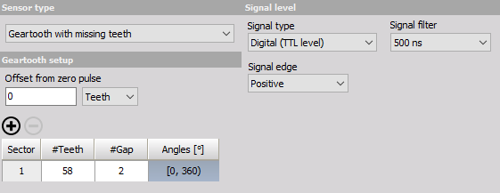
For these sensors, we define the number of teeth (#Teeth) and the gap lengths (#Gap).
Example - 60-2 gear with missing teeth
The example in the picture below shows the settings for 60-2 geartooth (meaning, the geartooth has 58 teeth in succession and then 2 teeth missing for the gap). If the gap would not be there, the geartooth would have a total of 60 teeth, but two of them are missing to create a gap.
Example - 14-2 gear with missing teeth
Another example is sketched below for a gear that should have had 14 teeth but are missing 2:
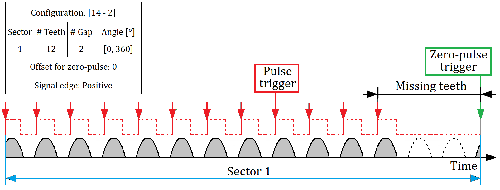
Note, that the Zero-pulse trigger is located at the first pulse trigger after the missing teeth interval.
Example - 60-2-2 gear with missing teeth
If we would like to enter a 60-2-2 sensor, we first need to click on + button above the sector grid. This adds a new “sector” to our geartooth definition. Next we change cells under #Teeth column to contain 28, so the sum of all the numbers is the total number of teeth.
Example - 14-2-2 gear with missing teeth
Another example is sketched below for a gear that should have had 14 teeth but are missing 2 + 2:
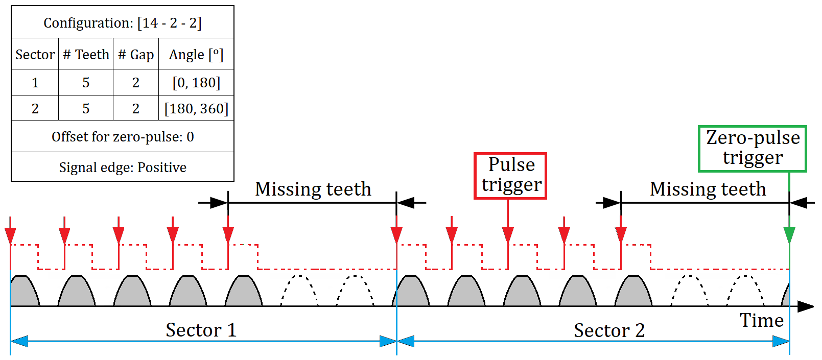
Note, that the Zero-pulse trigger is located at the first pulse trigger after the last missing teeth Sector. The Zero-pulse trigger is offset from the first sector after acquisition start, since the sectors here are symmetrical and therefore indistinguishable. With indistinguishable sectors it is only possible to determine sectors relative to acq. start.
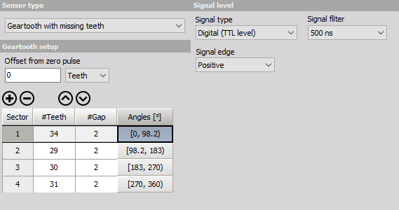
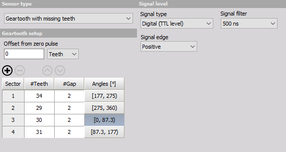
Example - Asymmetric 132-2-2-2-2 gear with missing teeth
Dewesoft also supports sensors with gaps asymmetrically (arbitrarily) spaced around the geartooth. To create such a sensor, simply create new sectors by clicking + button and filling out the #Teeth column with however many teeth appear in that specific sector. Picture below shows and example definition of a geartooth with 4 sectors: one with 34 teeth, then 29 teeth, then 30, and finally 31 teeth, each separated from the next with a gap of size of 2 teeth, for a total of 132 teeth.
Example - Asymmetric 18-2-1-2 gear with missing teeth
Another example is sketched below for a gear that should have had 18 teeth but are missing 2 + 1 + 2:
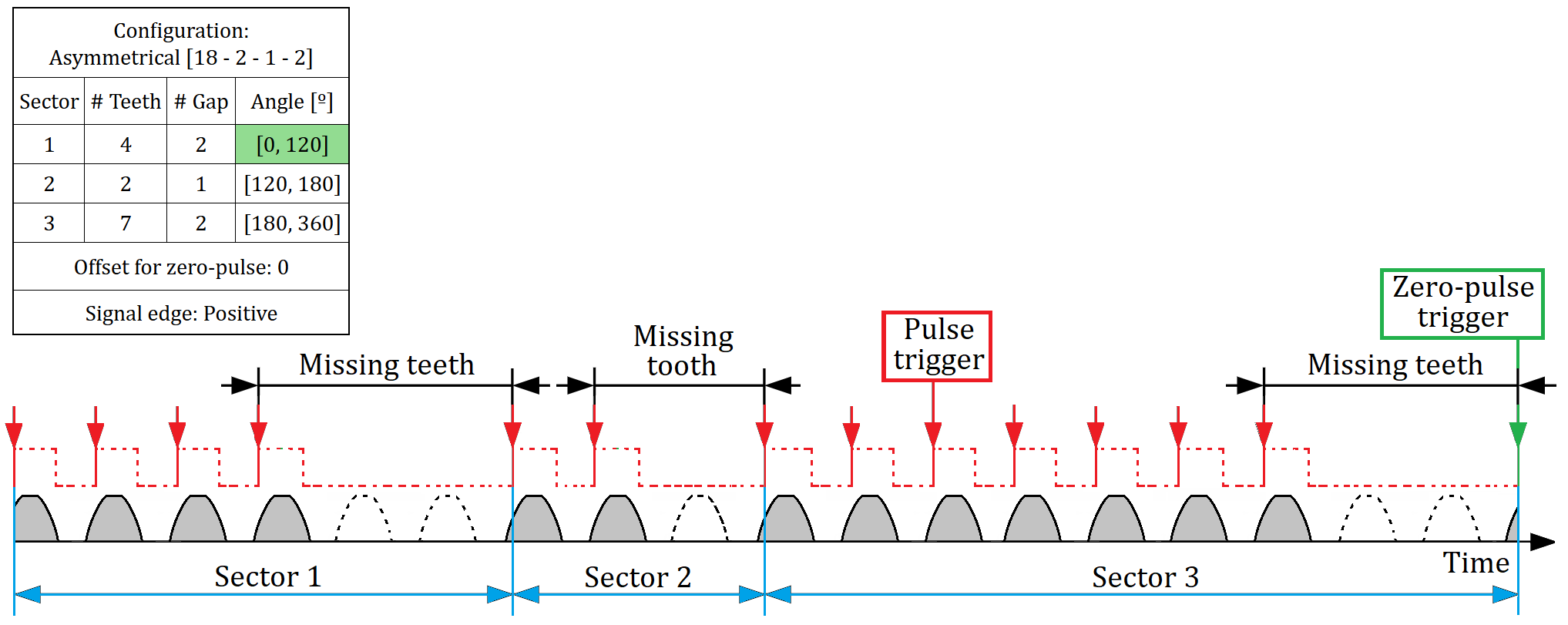
Note, that the Zero-pulse trigger is located at the first pulse trigger after the last missing teeth Sector. In this case, this is also at the beginning of the selected Sector, indicated in the sketch with a green background - having the 0-phase position.
Example - Asymmetric gear with changed Zero-pulse Sector - 1
The ordering of the sectors has to coincide with the actual physical geartooth. If we want to change the order of the sectors, we can select a row in the sector grid by clicking on it, and using up and down arrow buttons above the grid to move the row up or down respectively.
One of the sectors must be defined as the “zero pulse sector” - that is, the start of the first tooth in this sector is where the 0 degrees of the geartooth is. We can change the zero pulse sector by clicking on the cells under Angles column. The text in the cells specify the span of angles (in degrees) covered by the corresponding sector.
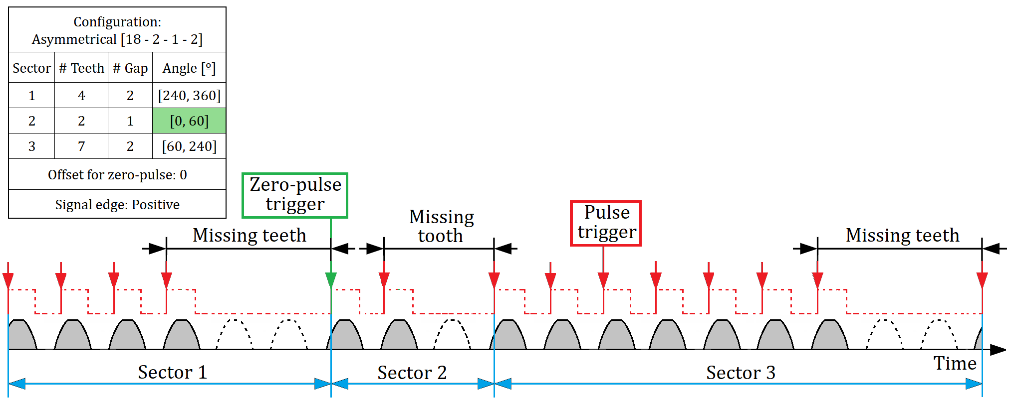
Example - Asymmetric gear with changed Zero-pulse Sector - 2
Another example is sketched below for an asymmetric gear that should have had 18 teeth but are missing 2 + 1 + 2. Here Sector 2 is now selected as the Zero-pulse sector:
And below Sector 3 is selected as the Zero-pulse sector:
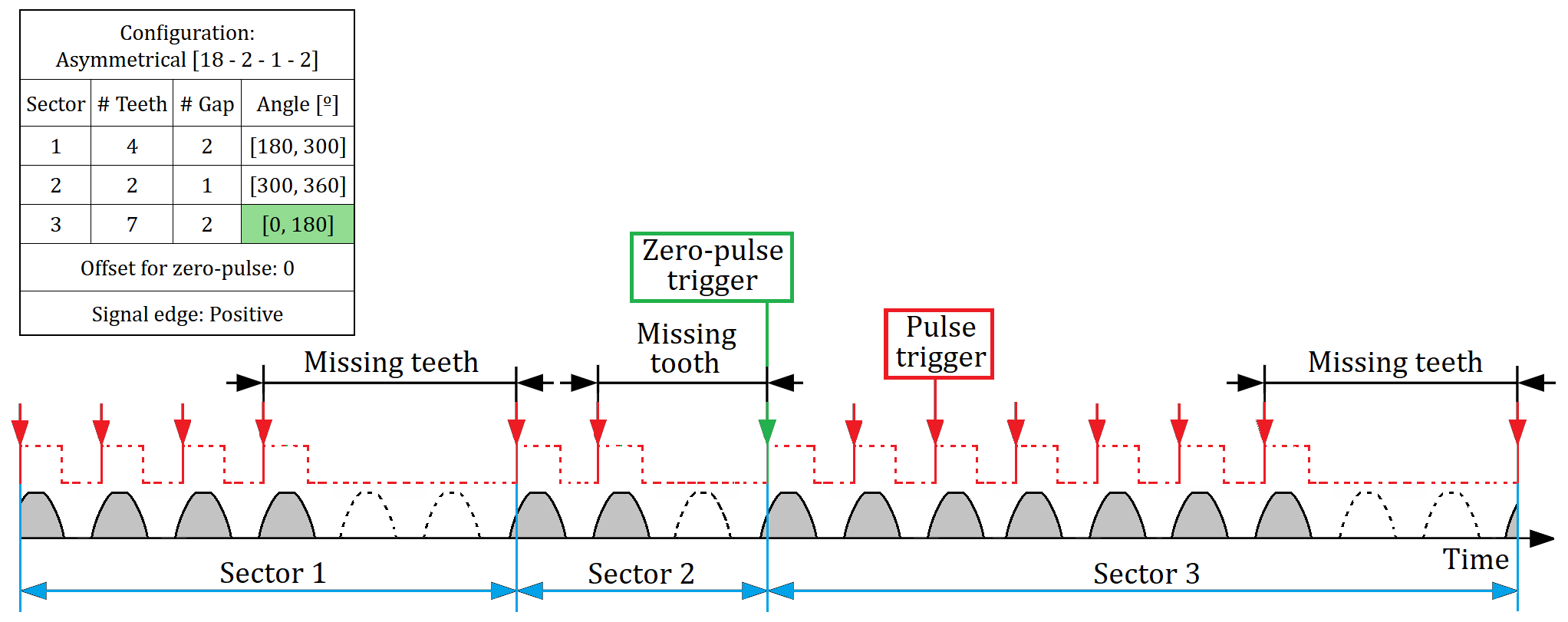
Note, the Zero-pulse is located at the beginning of the selected Sector, indicated in the sketch with a green background - having the 0-phase position.
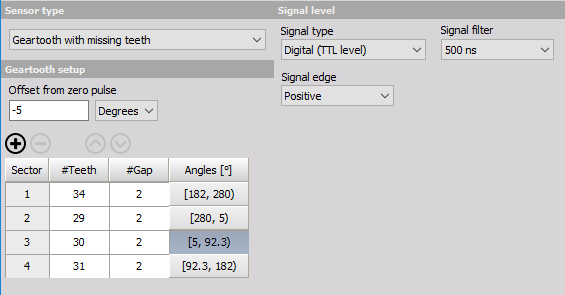
Example - Asymmetric gear with changed Offset from zero pulse
We can set the additional offset from the zero pulse. This can be useful if the actual zero is not located on the first tooth, but instead somewhere else on the geartooth (relative to the zero pulse sector). We can specify the offset in terms of either teeth, or degrees. So, for example, if geartooth has its actual 0 five degrees before the zero sector, we could enter “-5” and choose “Degrees” in the dropdown. As an alternative interpretation, this means that at the start of zero pulse sector the geartooth is rotated 5 degrees.
Example - 12-2 gear with changed Offset from zero pulse
Another example showing how changed Offset from zero pulse affects the phase data is sketched below:
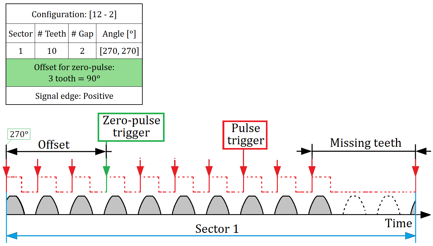
Note, that an offset of positive 90 deg will move the Zero position 90 deg forward in time. This will be the new 0-phase position. This also means that the start position in the sketch is now located at a phase of 0 - 90 = 270 deg.
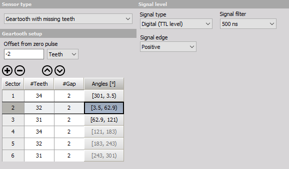
Example - Symmetric gear with changed Offset from zero pulse
In case the geartooth is symmetrical, the “zero pulse sector” can only be one of the sectors within the first “supersector” that repeats on the geartooth. That is so because it is impossible to determine which “supersector” the geartooth starts rotating with at the start of measurement, so Dewesoft simply assumes it is always the first one. For example, geartooth 60-2-2-2 is such a symmetrical geartooth with “supersector” composed of just one sector with 18 teeth, and we can only select the first sector as the zero pulse sector. Another example would be a geartooth with 34, 32, 31, 34, 32, and 31 teeth, where “supersector” of sectors with 34, 32, and 31 teeth repeats twice over the entire geartooth. In this case we can select any one of the first three sectors as the zero pulse sector:
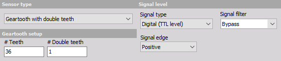
Geartooth with double teeth sensor settings
For these sensors, we define the number of teeth and the number of double teeth. The example below shows the settings for 36+1, a Geartooth with 36 teeth and one double tooth.
Another example is shown below for a gear with 13 teeth and 1 double tooth:
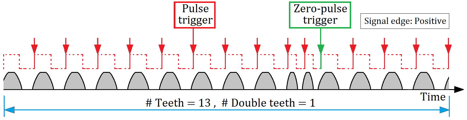
Note, that the Zero-phase trigger is located at the first Pulse trigger after the double tooth.