LIN BUS
LIN - Local Interconnect Network is used in the Automotive industry for the communication between vehicle components. It is a single-wire bus with a maximum communication speed of 19.2 kbits/s. LIN network consists of a maximum of 16 connected nodes. One node, named the master node, controls the traffic by sending message requests to which slave nodes reply with the requested data.
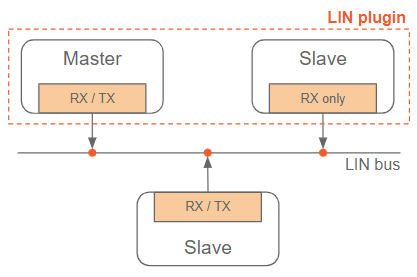
NOTE: Dewesoft LIN bus module can assume the role of master or listen-only slave node
Supported devices
- LIN interfaces produced by Vector Informatik GmbH
Prerequisites
- Latest Vector driver installed and the computer rebooted,
- connected Vector LIN capable device,
- Dewesoft X3 SP7 or newer software installed
- LIN bus extension added to Dewesoft.
Licensing
The plugin requires a valid DEWESoft® LIN BUS license. To test the plugin, you can use an Evaluation license.
Hardware setup
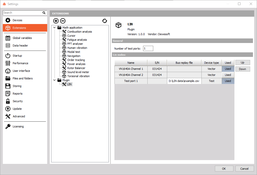
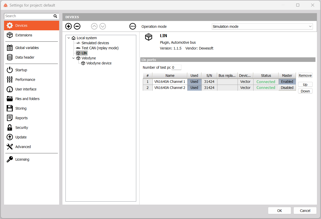
If all prerequisites are met you can proceed to hardware settings, where under extensions you will find LIN settings. All Vector LIN capable devices will be displayed here with an additional option for selecting the number of test ports. Each LIN channel is accompanied by a serial number for easier identification, when using multiple devices.
In DewesoftX version before 23.2 the Lin plugin must be added from Extensions like shown on the image below:
DewesoftX 23.2 and newer has the LIN plugin under devices, plugin is added with + button:
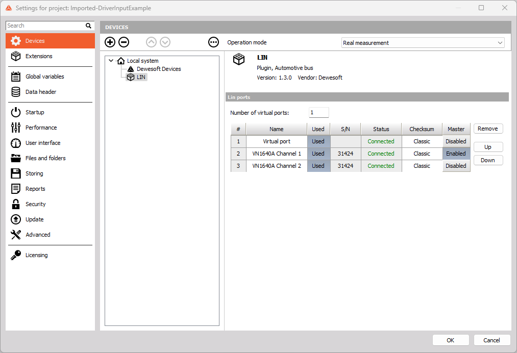
By using up and down buttons, located in the upper right corner, you can change the order in which used ports will be displayed in LIN setup.
NOTE: You can use one LIN physical channel with only one application. If some other application is using LIN channel, it will still be displayed in the grid, but set to locked.
Test port
As previously mentioned, you can select the number of test ports, which are meant for evaluation, quick tests and LIN setup configuration, without needing to connect actual hardware to your computer. Test ports support bus replay files, which simulate actual bus traffic from a file. Double mouse click on grid cell will open file dialogue, where you can select appropriate CSV file. If selected file does not exist or it’s not correctly structured, cell background colour will change to red.
Bus replay file
You can create bus replay files by hand. The structure is pretty straight forward. The first line is a header line, which must always be the same as the example below. Rows following are definitions of LIN bus traffic, consisting of the following values:
- Identifier - unique LIN frame identifier\,
- Timestamp - time in milliseconds since the start of measurement and
- Data - LIN frame data payload in little-endian format, meaning LSB is stored first and MSB last. Bytes are defined in hexadecimal notation. Maximum payload length is eight bytes. Missing bytes are interpreted as zeros (0x00).
NOTE: Data bytes must be delimited with tabulator key.
Example:
| Identifier | Timestamp | Data |
|---|---|---|
| 0 | 105.762 | 14 00 54 01 c0 |
| 1 | 112.307 | 00 78 00 46 00 00 c0 |
| 0 | 205.584 | 14 00 54 01 c0 |
| 1 | 212.161 | 00 78 00 47 00 00 c0 |
| 0 | 305.629 | 14 00 54 01 c0 |
| 1 | 312.188 | 00 78 00 46 00 00 c0 |
| 0 | 405.825 | 14 00 54 01 c0 |
LIN Slave setup
NOTE: From now on, we will be referring to LIN ports as LIN nodes, as they are already a part of LIN bus as listen-only LIN slaves
When you are done with hardware settings and you have at least one port set to used, you will be met with following LIN settings:
- LIN node name - you can rename the LIN node for easier identification. Default LIN node name is set to port’s name.
- Bus speed - the speed of data transfer on LIN bus. This setting is very important, as you will not be able to read any data if speeds will mismatch.
- Frame / Signal configuration - configure LIN frames you want to listen to.
- Import / Export - import and export of LIN frames on the currently selected LIN node. You can also import from LDF - LIN description file.
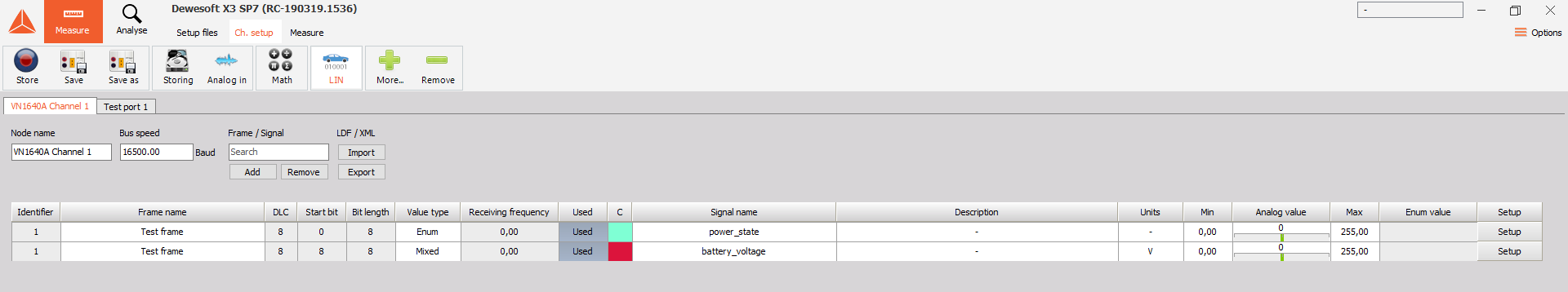
In setup mode, LIN node is already listening to all the traffic on LIN bus and decodes frames, which you already defined. So you can see the live preview of decoded data for each signal, which helps you determine if decoding is correct. You can edit some frame/signal settings directly from the grid (Frame name, Value type, Signal name, etc.), other settings are available by clicking on the Setup button. More on that in the following section. You can toggle signal’s Used property, which will enable or disable dewesoft channels belonging to that signal.
Frame / Signal configuration
Under Frame / Signal section you will be able to:
- Search by all cell values,
- Add new frame definitions and
- Remove multiple selected signals in the grid.
When you click on Add button, a new window will appear. It is divided into two settings groups.
- Frame setup, where you can set frame specific settings:
- Name - change frame name\, for easier identification\,
- Identifier - unique LIN frame identifier\,
- DLC (data length count) - expected frame data length in bytes and
- Signal list - add\, duplicate or remove signals.
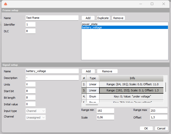
- Signal setup, where you can set signal specific settings:
- Name - change the signal name\, for easier identification\,
- Description - add an additional signal description\,
- Units - analog data units\,
- Start bit - start bit of signal’s data within frame’s data payload (byte1 = 0..7\, byte2 = 8..15 ...)\,
- Bit length - signal’s data length in bits\,
- Value type - you can choose between analog only\, enum only and mixed data decoding\,
- Min & Max value - used only with analog decoding. Define raw min and raw max value\,
- Linear ranges - add/remove multiple scaling ranges and
- Enum values - add/remove multiple enumeration values.
LIN Master transmit
In order to set a device as a LIN master perform the following actions:
- Proceed to the hardware settings section and navigate to the “Devices” tab.
- Locate the relevant LIN device in the list and set it as a master by toggling the switch button in the “Master” column.
When enabling transmit functionality for a frame, you need to execute the following steps:
- Enter the frame setup mode by clicking on the “Setup” option corresponding to the desired signal in the signal overview window.
- To enable transmit functionality for the frame, check the box labeled “Enable Tx.”
- In the signal setup, choose an input channel from the options “Channel” or “Constant.”
- Depending on the previous choice, either select a specific channel or specify a constant value.
- Repeat steps 3 and 4 for each signal of the frame. If these steps are not performed, the default values will be “Channel” for the input channel and an “Unassigned” channel value.
- Once you have configured all the signals, confirm the settings by clicking the “OK” button.
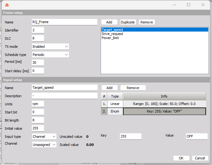
Before transmiting constant or channel value it needs to be descaled using aplicable linear scaling and rounded to the closest unsigned integer. Thats why there are labels showing both current unscaled and scaled value which will be recieved by other nodes connected to the network.
NOTE: Since unscaled value must be rounded to the closest whole positive number this means that current constant or channel value might differ to the actual value received by other nodes in the network
Data decoding
Consider LIN frame with four bytes of data (LSB = A, MSB = D):
| Byte A | Byte B | Byte C | Byte D |
|---|---|---|---|
| 1010 1011 | 1100 1101 | 0001 0010 | 0011 0100 |
From frame’s data payload we extract the signal’s raw values
| Start bit | Bit Length | Raw value |
|---|---|---|
| 0 | 5 | 0 1011 |
| 5 | 16 | 1001 0110 0110 1101 |
| 21 | 11 | 001 1010 0000 |
You can choose between multiple decodings:
- Analog
The raw value is extracted from frame data and it is checked against defined linear ranges. If raw value is in range (raw min & raw max inclusive), then scale and offset are applied by the following formula:
value = scale * raw_value + offsetValue is then saved to an analog dewesoft channel, which has the same name as signal Ex.: battery_voltage. - Enum The raw value is extracted from frame data. If any defined enum value’s key equals to raw value, then that value is saved to a discrete dewesoft channel, which has the same name as the signal but postfixed with “discrete” _Ex.: battery_voltage_discrete.
- Mixed Both previously described decodings. Two dewesoft channels per signal (analog and discrete).
Import / Export
When you are done setting up LIN frames, you can easily export them to an XML file, by clicking on Export button. You will be met with save file dialogue, where you can choose the file name and location. All LIN frames from currently selected LIN node will be saved to that file. That includes all dewesoft channel properties.
Importing LIN frames from file to the existing list can be done by clicking on the Import button. You will be met with open file dialogue, with the option to select between two file extensions: LDF and XML. Choosing XML will let you import files you or somebody else previously exported, choosing LDF is described in LDF import section.
If there are any collisions between existing and imported frames (the same frame identifier), you can choose to overwrite existing frame with imported one, or you can just skip importing that frame. You can also choose options Yes to all or No to all which will do the same for all detected collisions.
LDF import
LDF - LIN description file contains the configuration of a particular LIN network. It contains a lot of data like master schedule tables, publishers, subscribers, frames, signals, bus speed etc. So if you have a LIN description file for your LIN network, you can save a lot of time, by importing all frames and signals to currently selected node in setup. If bus speed defined in setup mismatches with bus speed defined in LDF, you will be prompted, which one you prefer to use.