License
Enable plug-in / Extension
PCM
The PCM Plugin includes the software Frame sync and Decommutation for PCM data sources. These sources can be from hardware including the DewesoftX Frame Sync box, Chapter 10 Plugin, or third-party hardware. The PCM plugin source is only needed so the Plugin knows where that data is coming from. As long as its PCM data it is all processed the same by this plugin. This Plugin will do a full software frame synchronization on the PCM data source along with process embedded PCM streams. Then the Decom section allows the user to enter individual parameter information along with the scaling units. Then this data can be combined with many other data sources brought into DewesoftX software as long as the time source is all the same.
Initial plugin setup
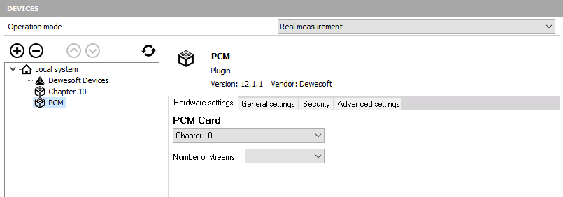
After the DewesoftX software has been properly installed, you must set up the PCM within DewesoftX. To do this, please run DewesoftX. Go to the Settings menu in the top right of the screen and then select Hardware Setup. When you do this, the Hardware settings dialog box will appear.
Click on the Plugins button and you will see the list of all the Plugins installed on your computer. If you open this screen and you do not have anything listed please refer to the steps below.
- Make sure you selected to install all the Addons when running the installer. You can check by finding your DewesoftX folder on your hard drive. Then look in the Bin/V7_1/Addons folder. If this is empty please re-run the installer.
- If your Addons folder has files in it please hit the register plugins at the bottom of the hardware settings screen.
NOTE: Depending on IT restrictions you might have to exit the software and run it as an administrator.
Locate the PCM plugin in the list and select change the unused to used to activate it. The PCM Card source selector gives you the option to choose from No device, Test mode (replay mode), and Tarsus PCM card, Chapter 10 and DewesoftX USB:
- No device – This is for when you have no PCM source at all and wish to see the setup screens for the PCM plugin.
- Test Mode – This is an Engineering troubleshooting tool with another ventors binary image file.
- Tarsus PCM Card – This is for when you have a Tarsus card from Ulyssix Technologies, Inc. installed and want to process raw PCM data.
- Chapter 10 – This is for when you want the PCM plugin to look at the DewesoftX Chapter 10 plugin for its PCM data source.
- DewesoftX USB – This is for when you are connecting a DEWESoft Frame Sync device.
The General settings selector allows you to select several settings to configure the software to your application.
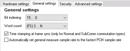
- Bit Indexing: allows the user to define the order the bits are counted in the Decom. The options are 15…0, 0…15, or 1…16.
- Word Count: This setting determines where your frame sync pattern falls in your word count. The options (FS)1…N means the first word after frame sync is word 1 in the minor frame. (FS)3…N describes the first word in the frame sync pattern as word 1.
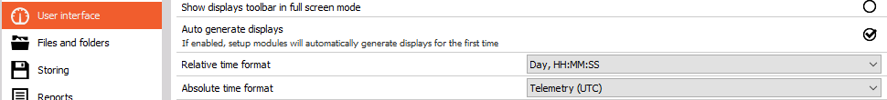
The last thing to do is change the absolute time format. Go to Settings, select the User interface tab, and change the Absolute time format to Telemetry (UTC).
Working in the PCM Plugin
Configuring the Bit Sync
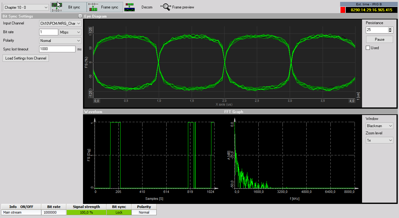
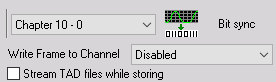
Go to the Ch. setup screen either by clicking the Ch. setup tab in the top toolbar or by pressing F2 on your keyboard. The setup screen will be shown. Click the PCM tab and then press the Bit sync button.
On this screen, you set up the channel source information. Depending on your data source the options might change. With the Chapter 10 input source, you will be able to load which PCM channel source and set up the bit rate unless it is in the TMATs section of your stream. Then you can click the “Load Settings from Channel” button. This will set up the data and frame sync information if it is included.
If you are using the DEWESoft Frame Sync box you will need to tell the software a little bit more information about your stream including bit rate, code type, polarity, etc. The Eye diagram will give you simulated graphics when looking at chapter 10 and then it will be a scope of the data when working with any other hardware.
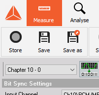
If there are multiple PCM channels sources inside a single system they will run and are set up independent of each other. Each stream can be selected by the drop-down menu shown below:
Eye Diagram
This display shows the incoming PCM stream in the classic “eye diagram” graph (Simulated in Chapter 10 mode).
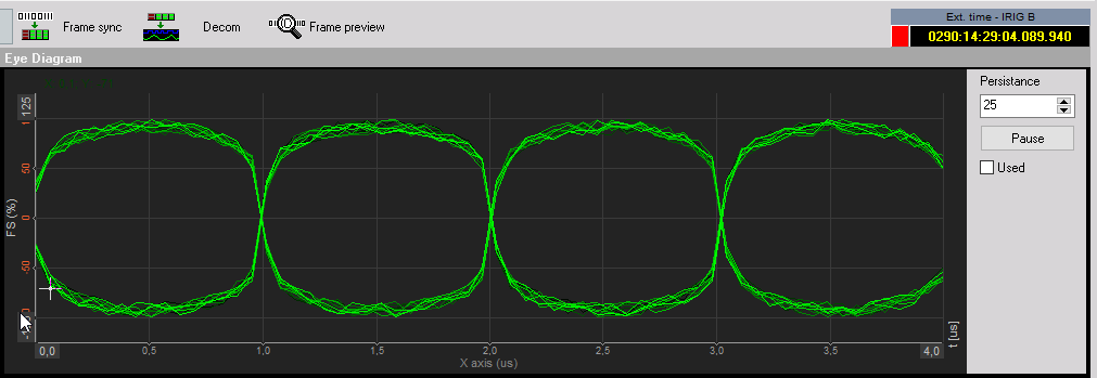
Using the Persistence selector, you can set how many plots are kept on the screen at once. The default setting is 25 and generally provides the best visual reference. You can increase the persistence to 50 or 100, but this takes more computer memory and also takes longer to update the
display. The recommended setting for most applications is 25.
Use the Pause button to temporarily freeze the eye diagram for visual study. Press this button again to resume the display updates. The used button allows you to view your eye pattern in a 2D Graph in measure mode.
Waveform Diagram
This display shows the incoming PCM stream (Simulated in Chapter 10 mode) in a conventional Y/T (amplitude versus time, i.e., oscilloscope type) graph, where the amplitude is shown in percentage, and time is shown in milliseconds (ms):
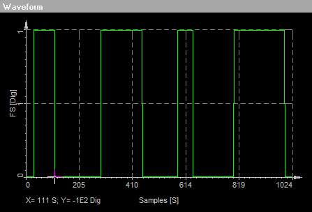 You can hover the mouse over the waveform and the display will calculate the amplitude (vertical Y
axis), the time (horizontal X-axis), and show them numerically at the bottom of the graph.
You can hover the mouse over the waveform and the display will calculate the amplitude (vertical Y
axis), the time (horizontal X-axis), and show them numerically at the bottom of the graph.
FFT Diagram
This display shows the incoming PCM stream (Simulated in Chapter 10 mode) in an FFT (magnitude
versus frequency, i.e., FFT/spectal) graph, where the magnitude is shown in decibels (dB), and the
frequency is shown in Hertz (Hz, kHz, or MHz).
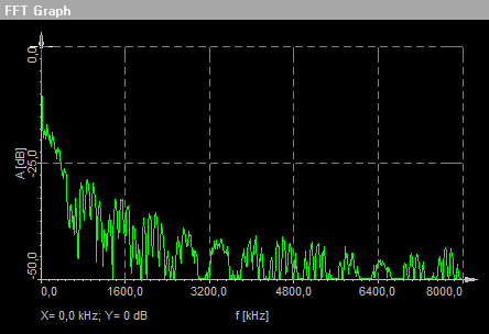
You can hover the mouse over the waveform and the display will calculate the magnitude in dB (vertical Y-axis) and frequency (horizontal X-axis) and show them numerically at the bottom of the graph.
You may select the window type for the FFT display and the zoom level from the drop-down menu.
Rectangular does not influence the FFT decomposition at all, while the other selections are industry standard algorithms used for biasing the lobes of the FFT analysis in order to improve the calculations based on different signal types.
Reference Bar
At the bottom of the bit sync setup screen is a reference bar which shows some important
parameters:

The core elements, shown here, are also shown when you change to the other setup screens. These include:
- Info ON/OFF indicates which stream is being monitored.
- Bit rate shows the bit rate for the selected stream.
- Signal strength shows the strength as a percentage for the selected stream.
- Bit sync shows the status of the signal lock on the selected stream.
- Polarity shows the current polarity (Normal or Inverted) for the selected stream
The headers of the parameters called Bit rate, Sig strength, Bit sync, and Polarity are actually buttons that can be pressed in.
Any of these parameters whose header button is pressed in will become available channels in the Dewesoft display screens under the status folder of each card. This allows you to display it on the screen in a digital meter, status display, tabular display, recorder window, or in any of the graphical display widgets available within the software.
Configuring the Frame Sync
Go to the Ch. setup screen either by clicking the Ch. setup tab in the top toolbar or by pressing F2 on your keyboard. The setup screen will be shown. Click the PCM tab then press the Frame sync button.
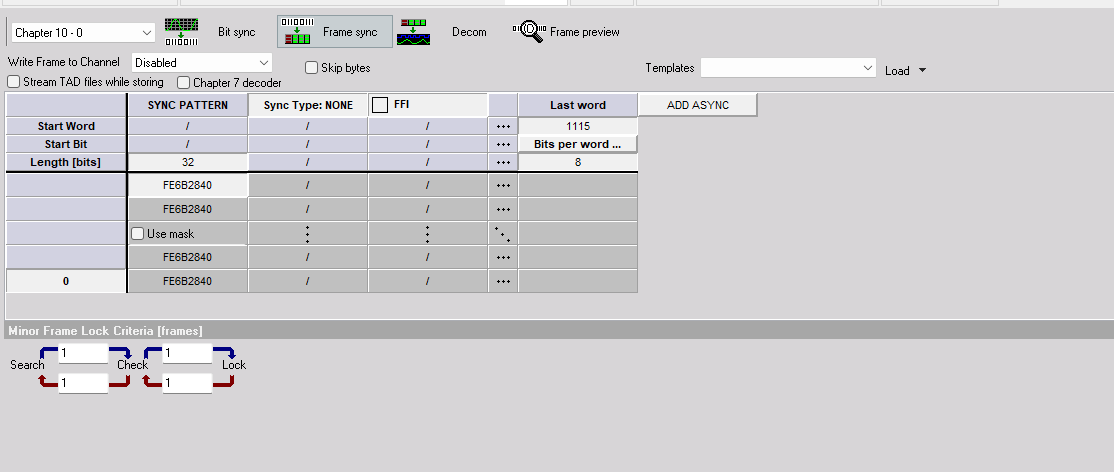
On this screen, you define the framing of the data within the PCM stream including the data length, frame format identifier, and any asynchronous embedded streams that may be present within the data. Other important settings include the frame lock criteria of the major and minor frames.
Write Frame to Channel or Stream TAD file while storing – Only use if not in Chapter 10 source. Use these checkboxes to tell the software to automatically archive data to the hard drive in a TAD (Ulyssix Data format) and/or C10 (IRIG Chapter 10 format if the system is licensed) format file when storing is underway.
Chpater 7 Decoder - This checkbox (additional licensed option to the PCM Plugin) allows the user to tell the software that this PCM stream is an IRIG 106 Chapter 7 PCM stream that has a payload of all Chapter 10 packets. This will then take the payload and create a data array for the Chapter 10 plugin to access to pull apart the embedded data.
NOTE: If using a Chapter 10 input source then you will need the Chapter 10^2 duplicate plugin to access. Please contact your local Dewesoft Support if not installed in the default Plugins.
Skip bytes - this checkbox allows you to set a number of bytes to keep and skip if you have a section of the PCM data that should be ignored.
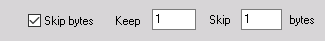
When you check the Skip bytes box, two fields labeled Keep and Skip will appear automatically. Simply click into these fields and enter the appropriate number of bytes. The byte count starts at the first byte in the frame sync pattern.
Templates - these are a time-saving method of saving a commonly used frame configuration for the frame sync. If there is a template available under the selector, simply choose it and then click the Load button in order to make it active.
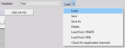
Or, to find another template to load, click the down arrow connected to the Load button, and this submenu will appear.
Moving into the Frame setup table to define the total number of bits in the frame sync pattern from
16 to 33 bits. In the example below, we have entered 32. To change this value, simply click into the
field and edit the value shown here.
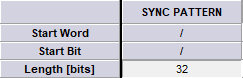
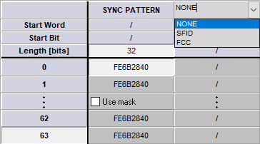
If you are using the IRIG Standard frame sync patterns the hexadecimal value will be automatically filled in. To change this value, simply click into the field and edit the value.
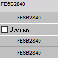
Select the Use Mask to set up a mask value that will cause the frame sync to ignore certain bits of the sync word. If using a mask: Enter a mask value using the following logic rules: logic high or ‘1’ in any bit position to ignore that bit. For example:
- Sync word size: 32 bits
- Sync pattern : FE6B2840 ( in Hexadecimal)
- Mask value : 0000F000 ( in Hexadecimal)
This example will cause the Frame Sync to ignore bits 12 through 15 during sync detection.
Any value in the PCM stream where the “2” in the FE6B2840 pattern is located would cause
a valid frame lock.
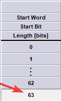
Now enter the number of minor frames per major frame (we have entered 63 in the screenshot
below). Simply click in the field and enter your number.
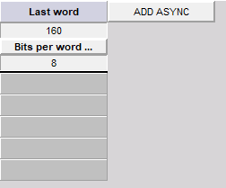
Now enter the Last word number in the minor frame (we have entered 160 in the screenshot
below). Simply click in the field and enter your number. Also, enter the number of Bits per word by
clicking in the field and typing the correct value. We have entered 16 on the screen below. This
setting is dependent on the Word Count setting under the Hardware Setup.
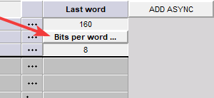
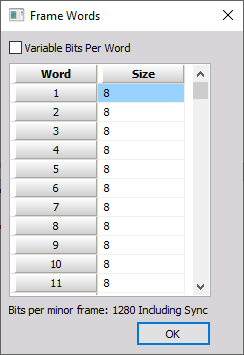
If your frame definition has variable bits per word simply click on the Bits Per word label. Then the
screen will open below to set up your word size.
NOTE: You can copy/paste from excel to make entry easier
Configuring the Sub-Frame
To configure the Sub-Frame Sync select either SubFrame ID counter (SFID), Frame Code Complement (FCC), or No minor frame sync (None).
Setup the SFID by entering the number of the word location in the frame of the SFID word. For
example if you have a 32-bit frame sync pattern with 16-bit words and the SFID is the first word after
sync then the start word is 3.

Then enter the start bit in the SFID word and the total number of bits.
Next, select the word order, up or down, using the toggle button. If it says Up, clicking it will change the direction to Down, and vice versa. Notice that the numbers will flip around to match your selection. In the screenshot above, we have selected Up, and therefore the numbers count up from 0 to 63. If we select Down, the numbers flip around to count down from 63 to 0:
Frame Format Identifier (FFI) word is used to allow the decom hardware to identify a
unique pattern in the PCM stream and perform a format switch.
If your data stream has one or more frame format identifiers (FFI’s), you need to check this box and
then enter the integer value corresponding to the word location in the frame, and then enter the
word length in bits, appropriate to your data:
When you put a checkmark in the FFI box, you will be prompted to enter the integer value of the FFI:
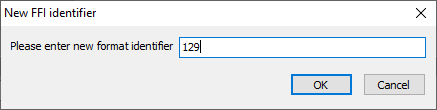
We have entered 129 into the dialog box and then clicked OK to set this FFI value.
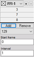
Enter the minor frame in which the FFI starts in the Start frame. For this example, it starts in the first minor so we enter 0.
Enter the Interval on how many minor frames must go by before we see the FFI again. In this example, we have a 1 so it will be every minor frame. If we placed a 100 for the interval we would see the FFI every 100th minor frame.
To add another FFI, use the Add button to create one. The same dialog box will appear allowing you to enter the value. As soon as more than one FFI exists, you can use the selector to choose among them and edit their properties.
Configuring Asynchronous embedded PCM Stream
If your PCM stream contains one or more asynchronous PCM streams, use the ADD ASYNC button to
add each one and then define it.
When you add an asynchronous stream, you must define where it is in the top level PCM stream. Enter the starting word and end word by clicking into the fields. If it is not a block of words in between the Start and end word you can use the Super comm to set up an interval.
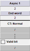
Use the ADD ASYNC button to add another asynchronous stream or the DEL ASYNC button to delete the selected one. With these controls, you may add and manage multiple asynchronous streams.
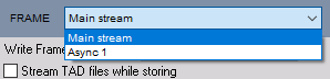
DewesoftX can process multiple asynchronous PCM streams at the same time. To set up each asynchronous PCM frame format use the drop-down menu below to select between the different streams.
Frame Lock Criteria
Frame Lock Criteria, i.e., the allowed transitions the hardware requires before changing the
frame status from search > check, and then from check > lock. Then the allowed transitions
the hardware requires before changing the frame status from lock > check, and check >
search. These must be integers representing a number of frames, and normally low values
are used of one or greater.
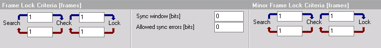
Sync window (bits) or also known as bit slips are the number of allowed bit errors in your total number of bits per minor frame.
Allowed sync error (bits) are the number of bit errors allowed in the frame sync pattern to remain locked to the data.
Use the Data In Search Mode selection if the user desires data regardless of Frame Lock.
Minor Frame Lock Criteria, i.e., the allowed transitions the hardware requires before changing the minor frame status from search > check, and then from check > lock. Then enter the number of allowed transitions the hardware requires before changing the frame status from lock > check, andcheck > search. These must be integers representing a number of frames, and normally low values are used of one or greater.
Configuring the Decom
On this screen, you will set up the system to decommutate the PCM stream. It sets up the software to extract individual parameter data from the PCM stream. The extracted data will be identified, combined, and processed which will then allow the user to visualize and analyze the PCM data.
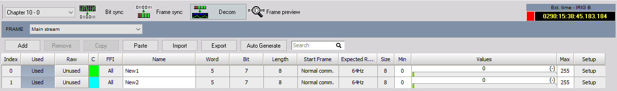
Notice the selector which presently says “Main stream” in the image above. You may use this to
select your asynchronous stream (if defined in the Frame Sync Setup), and the channels from that
stream will be shown on the main display. Click the selector and then choose the desired stream to
define parameters.

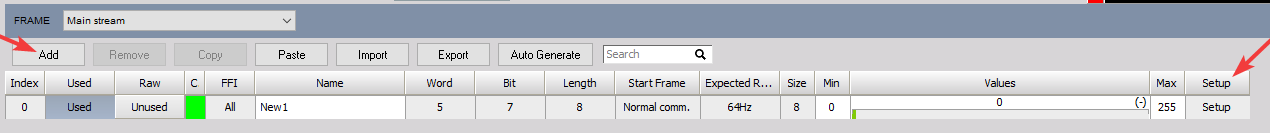
The Add/Remove buttons are to add or remove a new parameter to the decom setup.
The Copy/Paste buttons utilize the Windows clipboard to copy selected (the marked or darkened index number) parameters to the clipboard. The user can then paste these same parameters to other cards within the same system.
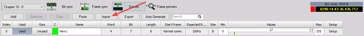
The Import button is for importing DewesoftX registered parameter lists for easy loading of
parameter setups.

Parameter table heading definitions
- Index - is the number from 0 to n (the total number of channels plus one) of the parameter
- On/Off - the used/unused status of the scaled output from this channel (when set to “Used”, it can be displayed and recorded)
- On/Off Raw - the used/unused status of the raw (unscaled) output from this channel (when set to “Used”, it can be displayed and recorded)
- C - (color) the color of this channel. It can be set here by clicking the color icon or on the Channel Setup screen PCM Plugin Users Manual PCM
- Plugin Manual – Version 1.0 – April 2014 Page 19 of 24
- Name - is the name of this channel. It can be set here or on the Channel Setup screen
- Word - is the word number in the minor frame of this channel
- Start frame – is the start frame of this channel, will be a number unless the channel is set to “Normal comm” instead of subcom or supercom
- Rate - is the update rate in minor frames of this channel
- Size – is the bit length of this channel
- Values – are a preview of this channel, scaled against the min/max values
Parameter Configuration
This is one of the most important aspects of the system because it is where you define the Parameters, or “Channels” which are to be extracted and made available for display and recording within the software.
NOTE: You can turn on or off the raw and scaled output values from each parameter independently. Simply click on the Unused button in the same row as the desired parameter to change it to Used, and vice versa.
NOTE: The total number of parameters should not exceed 10,000. If this limit must be exceeded, an alternative solution would be to use multistreaming across multiple PCs and perform decommissioning in parallel.
Press the Add button to open a new channel setup window or modify an existing channel by
pressing the Setup button at the end of each parameter’s row.
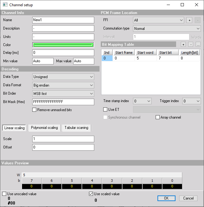
Channel Info: here is where you can set up the top-level properties of this channel.
- Name - enter a name for this channel. This is what will be displayed in the caption in measure mode
- Description - (optional) enter additional info about this channel
- Units - enter the engineering units for this channel (V, A, degrees, PSI, etc.)
- Color - click this windows widget to set the color for this channel.
- Delay - enter the number of milliseconds that this channel is delayed by
- Min value - set the display scale for this channel: low side (This is for Auto Widget setting along with Overload indicators)
- Max value - set the display scale for this channel: high side (This is for Auto Widget setting along with Overload indicators
NOTE: **The min and max values have no effect on the data being recorded. These fields only set the default display scaling. **
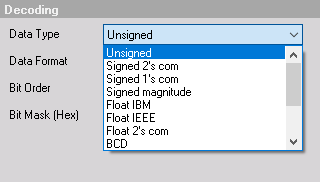
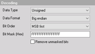
Decoding and Scaling: here you set up how this channel is interpreted by the software.
Date Type - This is how the data word extracted from the PCM stream is represented in memory.
When Two’s Comp or One’s Comp is selected, the data will be represented as positive and negative
values. These values will be sign-extended when extracted from the PCM stream. The Binary
selection will treat data as positive binary values with no sign extension.
Data format selects from between big endian and little endian.
Scaling values (A0, A1, A2, A3, A4, A5) you can enter the scaling values according to the formula shown below the fields, where: A0 + A1 * x + A2 * x + x + A3 * x * x * x … Enter as many scaling factor values as you need for this channel; leave the others with the default zeroes in them.
PCM Frame Location: you can set the commutation type and bit locations for this channel.
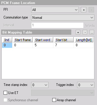
Commutation Type – Select from Normal, SuperComm, or SubComm for parameter type Interval – Used for your SuperComm or SubComm words. For SuperComm words this is the word the interval between the samples. For SubComm this is the minor frame interval in between samples Bit mapping table - here you define:
- Start frame – Is the minor frame number the parameter data starts
- Start word – Is the word number in the minor frame the parameter data starts
- Start bit – Is the start bit in the word where the parameter data starts
- Length - (in bits) of the number of bits in the parameter data
Bit Concatenation - where you need to combine bits from different parts of the frame to make one
parameter. Ex imbedded Time.
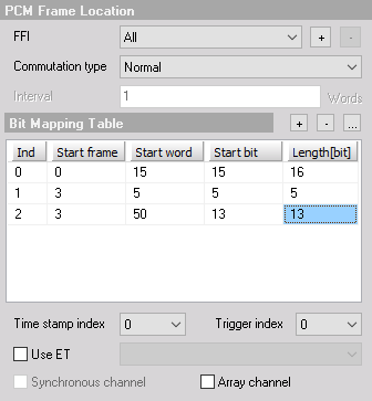
Use the [+] and [-] buttons to add indices to the bitmapping table. Then you can click within each value, in the newly created row o, You can also select any index number and then use the [] button to delete it.
Use the Trigger index if there’s more than one item in a bit mapping table; the user can select what is a trigger index for writing a sample to a DewesoftX channel.
Select ET (Embedded Time) to set-up embedded time in the PCM stream as a decom word. The user can define each BCD time digit to a specific nibble in the PCM word.
Select Synchronous Channel to create the Dewesoft channel as a synchronous channel, constant rate.
Select Array channel with channels that have more than one sample (n×m samples, in most cases it is vector) and is used for special calculations; for example, Missed Distance Calculations.
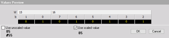
Values Preview – A very useful tool to look at the values preview at the bottom of the dialog to see the effect of your scaling against the real data. Also gives an overall view of the parameter as you concatenate bits together to build a parameter.
Importing a parameter list
You may import a list of parameters which has already been defined in a TXT, TMATs Files, and CSV import. Click the Import button as shown here on the decom setup screen:
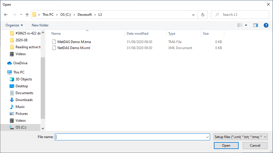
And you will be presented with the Open dialog box, where you can navigate your computer and locate the file that you would like to load:
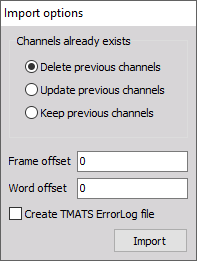
Once the file is opened, you can select different import options:
Frame Preview Screen
The frame preview screen gives you a clean look at the raw live frame dump of the major frame data in hexadecimal. The first minor frame with the minor frame time stamp starts at the top. The channel color labels show your parameter locations in the major frame.
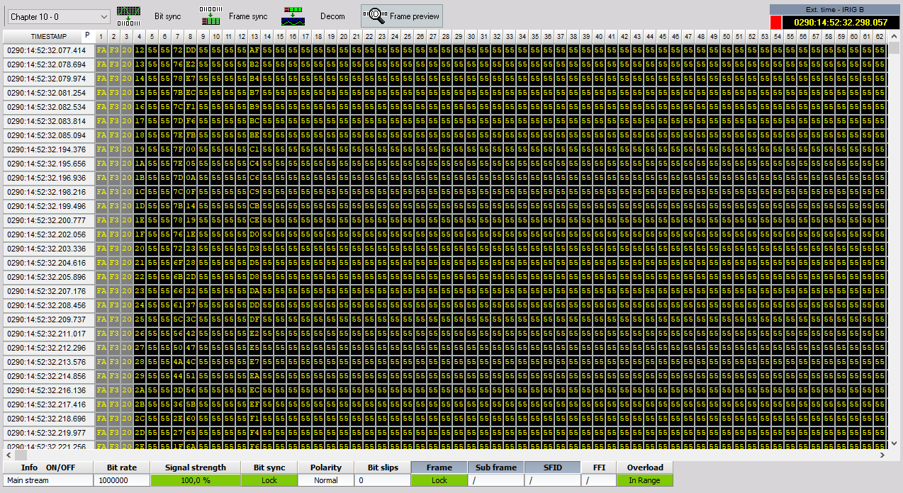
By clicking on a word in the major frame a window will appear giving detailed information on that individual word.
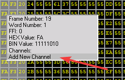
If that word is not defined as a parameter select: Add New Channel. This will automatically bring up the decom channel setup screen with the correct frame location information filled in.
Encoder Functionality
As of update 2021.1, an encoder feature has been added within the PCM that will allow the PCM channel one to be used as an encoder. This is to be used for outputting clock and data from the Dewesoft 2xPCM hardware.
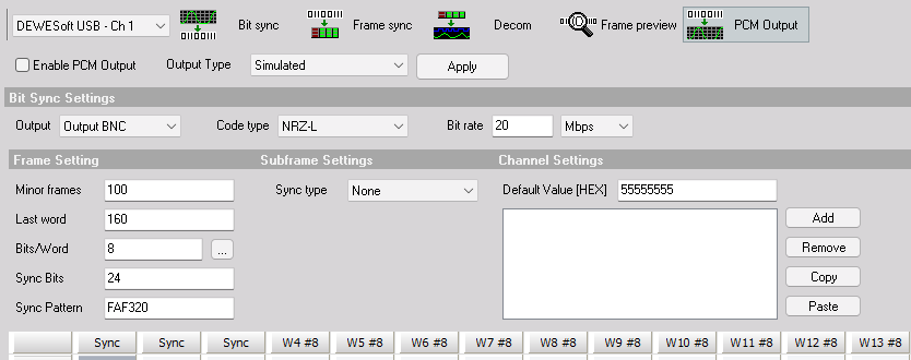
You will need to select the DewesoftX USB card and Ch 1. You will see a option on the far right named PCM Output. Clicking on this will open a new setup dialog.
You must check the radio box “Enable PCM Output” to turn on the function
Output Type- This can be simulated data, encoded data from the Dewesoft Analog to Digital hardware, or replay of clock/ data previously recorded.
Apply button- Any time that you make any changes within this window, you must click this to press the changes through
Output can be either BNC or diff connections on the 2xPCM box.
The remaining setup is standard to IRIG 106 Chapter 4 and can be configured to meet the testing requirements.
NOTE: If PCM output is enabled, input is not an option.
NOTE: PCM Output requires valid license PLUGIN-PCM-OUTPUT.