Torsional vibration
For more information about Torsional vibration take a look at the [Rotational and Torsional vibration manual]
Dewesoft Torsional vibration application module allows measure dynamic and static bending and vibration of the shafts. The torsional vibration also measures the twist of the shaft with higher RPM. With torsional vibration module two different parameters can be measured: rotational vibration and torsional vibration.
- Rotational vibration - is simply the dynamic part of rotation speed. If we measure the rotation speed of shaft with high precision, we will notice that in some regions of the run up we get high deviation of rotation speed. This is caused by angular vibration crossing angular natural frequency of the shaft. It is calculated with cutting off the DC component of the rotation speed or rotation angle.
- Torsional vibration - is an oscillation of angular motions (twist) which occur along rotating parts such as gear trains, crank shafts or clutches. We need two encoders to measure the torsional vibration, so the torsional vibration is actually a difference between angles of two encoders.
- Extract order - from Torsional vibration or Rotational vibration see -> Extract order.
To measure torsional or rotational vibration, we need a Sirius module with two counter inputs, because all other methods do not have precision needed to do this.
- Required hardware - Sirius with counter expansion, Dewe43
- Required software - Dewesoft DSA license (OPT-ORDTR and OPT TORVIB option) or 1 month Evaluation license.
- Setup sample rate - At least 10 kHz
Dewesoft Torsional vibration measurement is activated by selecting the Torsional vibration calculation in Modules menu. Ch.setup -> More… (Add module) -> Torsional vibration tab.
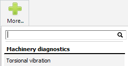
For instructions on how to Add new module see -> Setup -> Add module.
After selecting this option, a tab labeled Torsional vibration appears in the Dewesoft Setup screen (see picture below) to define and setup Torsional vibration module(s).
To use Torsional vibration module we don’t need to set anything on analog or counter channels.
Torsional and rotational vibration can be measured with either encoder (up to 3600 pulses per revolution) or special RIE sensor which has less resolution (up to 720 pulses per revolution) but is much less sensitive to vibrations which could damage standard encoders.
Two different procedures of Torsional vibration module setup are:
Rotational vibration setup
After add new Torsional vibration module screen like this will appear:
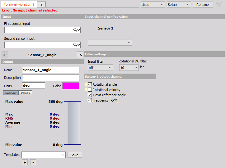
This screen has five main sections:
- Input channel - sensor selection
- Output channel settings
- Input channel configuration - for Sensor 1
- Filter settings
- Sensor output channel definition for Sensor 1
With using View Channel List button we can show different view on Torsional vibration module setup -> Channel list with all defined output channels.
Input channel - sensor
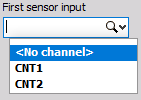
First of all select the input channel - sensor 1 (the first connected sensor) from the First sensor input drop down list.
Since we have connected in example above the first sensor to CNT0, we need to select it from list.
Please note that CNT1, CNT3 and CNT5 are not available, since they will be used internally to calculate exact frequency.
Input channel configuration
Since we only have one(first) Rotational vibration sensor connected, on Rotational vibration setup screen there is only one sensor 1 Input channel configuration section.
On this section we can set:
Sensor type - select the right Encoder sensor type from drop down list:

Both sensors must count in positive direction. If we use encoders, there is a chance that the counting direction of a sensor is Negative.

Input filter for the counters

Input filter is needed to prevent glitches and spikes on the signal, is also one important setting to prevent double counts. The Input filter can be set in a range between 100ns and 5μs. The optimal settings are derived from the following equation:
$$ \text{InputFilter [s]} \leq \frac{10}{\text{RPM}_{\text{MAX}} \cdot \text{PPR}} $$
- $\text{RPM}_{\text{MAX}}$ - max. revolution s per minute [s-1]
- $\text{PPR}$ - pulses per revolution [-]
Rotational DC filter needs to be set to cut the DC component of the RPM. We need to set the filter to include all wanted frequencies, but not too low, otherwise we will have static DC deviations on the output signal.

Sensor output channel

The Sensor 1 output channels can be:
- Rotational angle -filtered angle value of vibration
- Rotational velocity - filtered velocity vibration value
- X axis reference angle - the reference angle which is always from 0 to 360° and can be used as reference in angle based XY diagram
- Frequency [RPM] - frequency in RPM unit
Select desired option with checking box beside caption. For each selection in this section one separate output channel is created (see below).
Output channel settings
The lower-left area displays the output channel settings with fields like in the analog channel setup: Name, Units, Color, Min val and Max val, also symbolic display of signal values.
Torsional vibration module can have more output channels according to selection in Sensor 1 output channel. For each selection in this section one separate output channel with default name is created:
For Sensor 1 output channel section selected:
Rotation angle choice

Rotation velocity choice

X axis reference angle choice

Frequency [RPM] choice

Example:
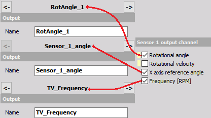
At least one output channels must be checked.
Use the Previous and Next buttons to navigate between the output channels in OUTPUT channel settings part of screen.


Channel list view
After adding new Torsional vibration module we can navigate to Channel list.
For help with Output Channel list see -> Setup -> Output Channel list.
When this button is selected on Rotational vibration module setup, Channel list screen with all defined output channels appear:

For information about Channel grid columns see -> Setup -> Channel grid.
Torsional vibration setup
Input channel - sensor
To measure the torsional vibration we need to select both input channels in torsional vibration setup.
Beside first input (channel - sensor 1) also second input (channel - sensor 2) from the Second sensor input drop down list must be select.
Since we have connected in example below the second sensor to CNT2, we need to select it from list.

Please note that CNT1, CNT3 and CNT5 are not available, since they will be used internally to calculate exact frequency.
After selecting a second input channel - sensor 2 screen like this will appear:
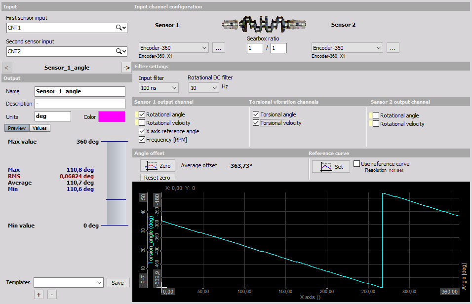
This screen has the following main sections:
- Input channel - sensor selection
- Output channel settings
- Input channel configuration - for Sensor 1 and Sensor 2
- Filter settings
- Sensor output channels definition for Sensor 1 and Sensor 2
- Torsional vibration channels definition
- Angle offset / Zeroing
- Reference curve configuration
With using View Channel List button we can show different view on Torsional vibration module setup -> Channel list with all defined output channels.
Input channel configuration
Since we have two (first and second) Torsional vibration sensors connected, on Torsional vibration setup screen beside setup for Sensor 1, a second Input channel configuration for Sensor 2 section appeared.
On these setups we need to separately define Sensor 1 and Sensor 2 properties:
- Pulses per revolution
- Sensor type
For information about Pulses per revolution and Sensor type settings see -> Rotational vibration setup.
Some configuration settings are common for both sensors:
- Input filter for the counters
- Rotational DC filter
Gearbox ratio - If we have gearbox in between sensors, we need to enter Gearbox ratio.

NOTE: Both sensors must be set to positive counting and both input filter must be set to same value!
Sensor output channels
Sensor 1 output channel
The Sensor 1 output channel is same as for Rotational vibration setup.
Sensor 2 output channels
The Sensor 2 output channels can be:
- Rotational angle - filtered angle value of vibration

- Rotational velocity - filtered velocity vibration value
Select desired option by checking box beside caption.
For each selection in Sensor 1 and Sensor 2 section one separate output channel is created.
Torsional vibration channels
The Torsional vibration channels can be:
Torsional angle - dynamic torsional angle that is the angle difference from sensor 1 to sensor 2

- Torsional velocity - difference in angular velocity from sensor 1 to sensor 2
Select desired option by checking box beside caption.
For each selection in this section one separate output channel is created (see below).
Angle offset / Zeroing
In Average offset field Angle offset (difference) is displayed. A click on the Zero button removes the angular difference (offset) between the two sensors (set angle offset to 0).

Reference curve
A click on the Set button records the current torsion angle over one revolution as reference. When Use reference is checked, the recorded reference is subtracted in angle domain from the current torsion angle. In this way you can overcome torsion errors caused by the sensors or their fixing.

Output channel settings
The lower-left area displays the output channel settings with fields like in the analog channel setup: Name, Units, Color, Min val and Max val, also symbolic display of signal values.
For help with Output Channel list see -> Setup -> Output Channel list.
Torsional vibration module can have more output channels according to:
- Sensor 1 output channel section
The output channel is same as for Rotational vibration setup.
Torsional vibration channels section
For on Torsional vibration channels section selected:
Torsional angle choice

Torsional velocity choice

- Sensor 2 output channels section
for on Sensor 2 output channels section selected:
Rotational angle choice

Rotational velocity choice

For each selection on these sections one separate output channel is created.
Example:
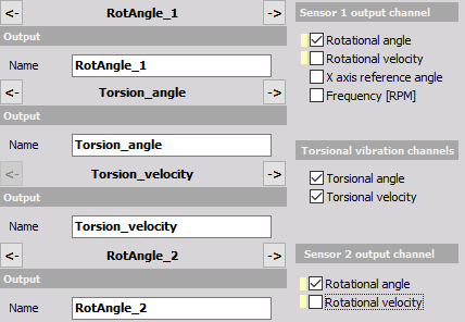
At least one output channels must be checked.
Use the Previous and Next buttons to navigate between the output channels in OUTPUT channel settings part of screen.


Channel list view
After adding new Torsional vibration measurements we can navigate to Channel list.
For help with Channel list see -> Setup -> Output Channel list.
When this option is selected on Torsional vibration module setup, Channel list screen with all defined output channels appears:

For information about columns in Torsional vibration channel list see -> User Guide -> Rotational vibration setup.
Extract order
NOTE: To extract orders from rotational vibration we need to add order tracking module. For frequency source we need to define the same counter input as in rotational vibration.
NOTE: To extract orders from torsional vibration we choose the Torsion angle or Torsion velocity or both for the input channel of order tracking math module.