Human vibration
Dewesoft Human vibration application module allows measurement of effect of vibrations to human body. Especially on work places exposed to vibrations there is a big chance of permanent damage to some parts of human body. The human vibration module provides measurements to be able to judge the risk of such damage.
Certification and conformity
- ISO 8041-1:2017 - General purpose vibration meters
- ISO ISO 2631-1:1997, 2631-5:2018 - Evaluation of human exposure to whole-body vibration
- 5349-1:2001 - Measurement and evaluation of human exposure to hand-transmitted vibration
- ISO/TR 18570:2017 - Supplementary method for assessing risk of vascular disorders
There are two types of measurements possible
- Whole body measurements - are measured with the help of the so called seat sensor, where we need to install the triaxial sensor in the rubber adapter on which we sit on.
- Hand arm measurements - is measurement of hand arm where the sensors are installed on special adapters for holding them on the handle or between fingers.
Both measurements are performed with triaxial accelerometers (it is very common to use 50 g sensors) and using special adapters. For working places with high vibrations (for example impact hammers) it is necessary to use high g sensors (500 g or more).
- Required hardware - Sirius, Dewe 43
- Required software - SE or higher + HBV option, DSA or EE
- Setup sample rate - At least 5 kHz
For additional help with Human vibration Application visit Dewesoft PRO training.
Add / New Human vibration module
For instructions on how to Add new module see -> Setup -> Add module.
Basic procedures of Human vibration application setup are:
- Human vibration module setup for applied hardware
- Calibration
Human vibration module setup
After we add a new Human vibration module a screen like this will appear:
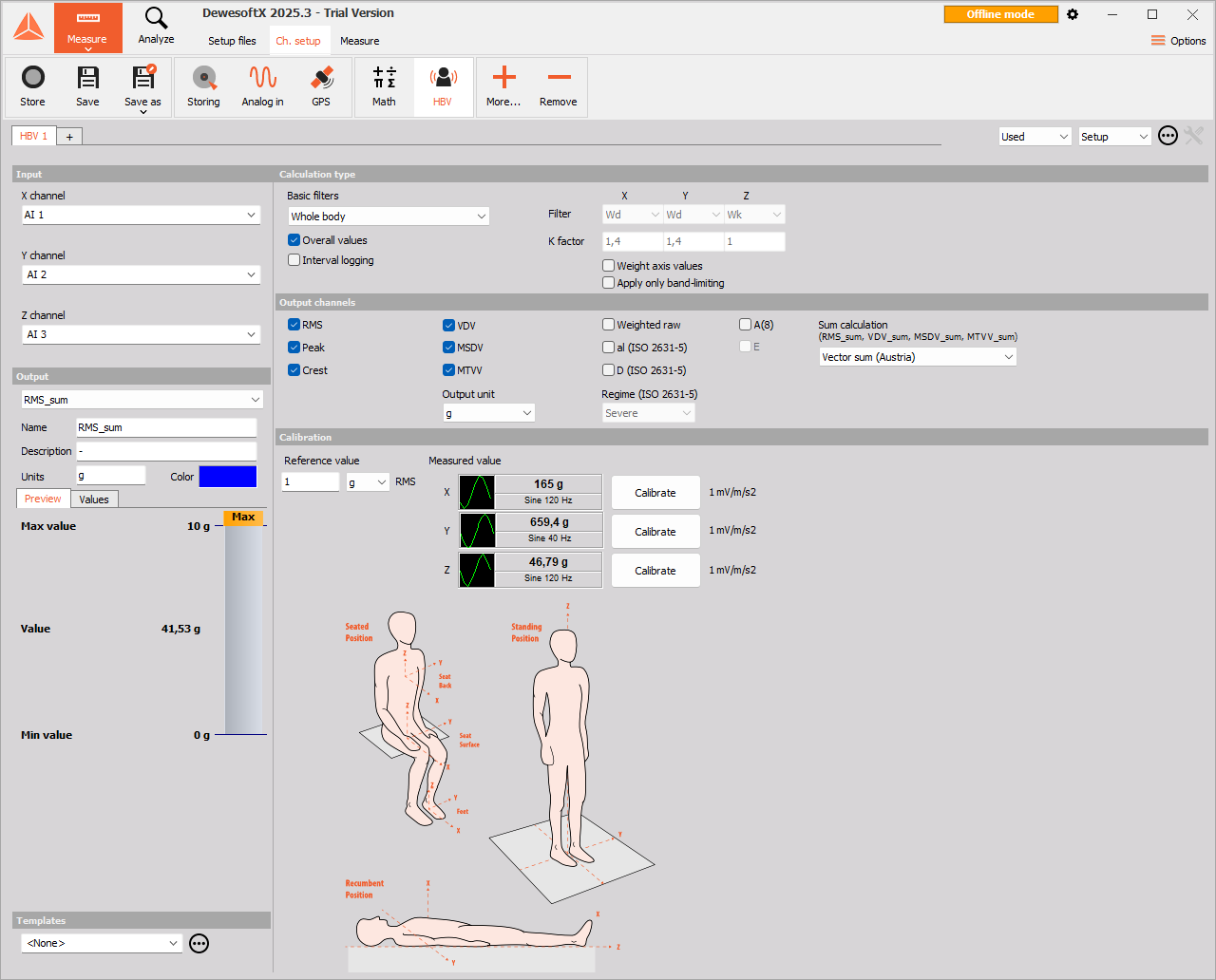
This screen has the following main sections:
- Input channel selection
- Calculation type
- Ouput channels
- Calculated parameters definition
- Triaxial accelerometer calibration
With using View Channel List button we can display a different view on Human vibration module setup - Channel list with all defined output channels appear.
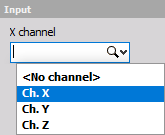
Input channel
First of all we need to assign the input channels to triaxial accelerometer sensor by selecting from drop down lists for x channel, y channel and z channel separately.
It is important that the z axis is a vertical direction since it is weighted differently than x and y.
Calculation type
On Calculation type section we have two parameters to define the measurement:
1. Measurement modes
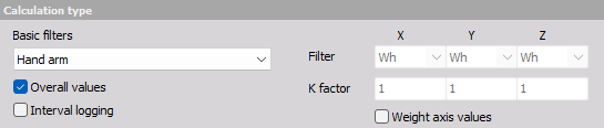
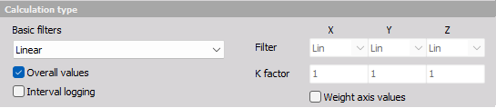
- Basic filters - Different modes define different Basic filters used to simulate the human response to vibrations. Those filters are defined from numerous measurements of natural frequencies of certain parts of the human body. Select desired mode from the drop-down list.
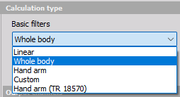
There are two basic modes of operation:
- Whole body mode (Individual Filter and K factor settings can’t be chosen, these are predefined).
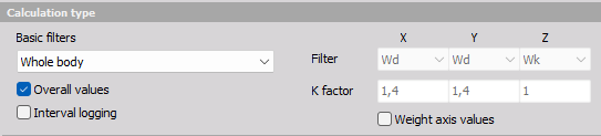
- Hand arm mode (Individual Filter and K factor settings can’t be chosen, these are predefined).
- Linear filter to check the measurement chain (Individual Filter and K factor settings can’t be chosen, these are predefined).
Custom filters
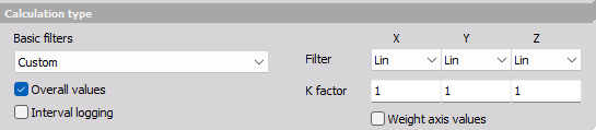
Filter X, Y and Z value: this individual value can be selected from the drop-down lists on the right side to do special measurements. Filters are defined as follows:
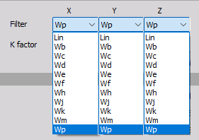
- Lin - unweighted linear
- Wf - motion sickness, z axis
- Wb - vertical whole body, z axis (older ISO 2631-4)
- Wh - hand arm, all directions
- Wc - horizontal whole body, x axis
- Wj - vertical head vibration, x axis
- Wd - horizontal whole body, x or y axis
- Wk - vertical whole body, z axis
- We - rotational whole body, all directions
- Wm - building vibration; all directions
- Wp - hand arm, frequency weighting factor recomended by ISO 8041-1.
With custom filter, we need to define a weighting K factor. This is a multiplication factor for each axis when calculation vibration sum.
NOTE: We need to take care about the high pass frequency limit of the sensor and used amplifier. For hand arm mode, the high pass frequency is 6.4 Hz, which is easy for any sensor. For the whole body, the frequency limit is 0,4 Hz, where we need to choose sensor carefully. We can also use higher filters (like 3 Hz), if we know there is no frequency content below this limit. This will help to perform measurement faster and with less error (lower frequency filters means longer settling times). A special care must be taken for Wf filter for motion sickness (for example on ships) where the frequency limit is only 0,08 Hz and we need a very special sensor to measure this low frequency vibration.
NOTE: The recommended sampling rate of the measurement also depends on the application. For hand arm the minimum sampling rate is 5 kHz, while for all the others 1 kHz is enough.
Weight axis values - will take the K factor into account when weighting each axis individually.

Apply only band-limiting - the calculated data will include only band-limiting filter (High pass filter plus Low pass filter), not the Wh filter (high pass filter, low pass filter, and filters that depend on weighting selceted).

2. Calculated parameters
On the lower part of Calculation type section choose type of parameter for calculation (at least one must be selected for calculated channels):
- Overall values - we have only one value at the end of the measurement
- Interval logging - the time interval for logging is defined.
- Both

For example if we select to have interval logging with 5 seconds interval, we will get a new value after each 5 second. After that the value is reset and the calculation is started again.
Output channels definitions
We can define the output channels, additionally to basic filters and k factor channels.
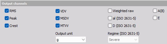
- RMS - calculate the root means square value of the weighted signal
- Peak - the maximum deviation of the signal from the from the zero line
- Crest - the ratio between the peak value and RMS value. Crest factor gives an impression about the spikes in the signal; pure sine waves have a crest factor of 1.41.
- VDV - fourth power vibration dose value
- MSDV - motion sickness dose value
- MTVV - the maximum transient vibration value, calculated in one second interval
- Weighted raw - full speed time signal weighted with chosen filter. We can use those channels for calculation of FFT or CPB spectrum.
- aI (ISO 2631-5) - the lumbar spine response from excitation measured in all three directions
- D (ISO 2631-5) - acceleration dose, measured from the lumbar spine response
- A(8) - is a daily dose of vibration from the standard. Whole-body vibration should be evaluated on the basis of the result of the daily dose of A (8) expressed as equivalent frequency-weighted acceleration within eight hours, and calculated as the highest value of RMS or VDV determined in three axes X, Y, Z.
- E - is exposure value, according to standard for hand-arm vibration.
NOTE: al and D are the values based on ISO 2631-5 which describes the calculations and the limits for lumbar spine response to vibrations. The base for this standard is that the professional drivers of buses or trucks are exposed to vibrations when driving on rough roads or over the bumps. Multiple shocks cause transient pressure changes at the lumbar vertebral end plates that cause damage after years of driving. al and D are enough to evaluate human vibration exposure according to ISO 2631-5.
Output channels settings
The lower-left area displays the output channel settings with fields like in the analog channel setup: Name, Units, Color, Min val and Max val, also symbolic display of signal values.
For help with Output Channel list see -> Setup -> Output Channel list.
Human vibration module can have more output channels according to:
Calculation type section
Basic filters: For each selected axis individually a Filter and a K factor channel is created. Each output channel is created with a default name and can be changed in output name row.
- Filter output channels

- K factor output channels

NOTE: These output channels are created in any case, though in Calculated parameters and Output channels sections none whatever choice is selected.
Calculated parameters section
These parameters have only influence upon creating output channels for calculated value selected in Output channels sections -> see below.
Output channels section
For each calculated and in this section selected value additional to basic filters channels one output channel for each axis individually is created.
Peak output channels
- For selected Overall values in Calculated parameters section:

- For selected Interval logging in Calculated parameters section:

Crest output channels
- For selected Overall values in Calculated parameters section:

- For selected Interval logging in Calculated parameters section:

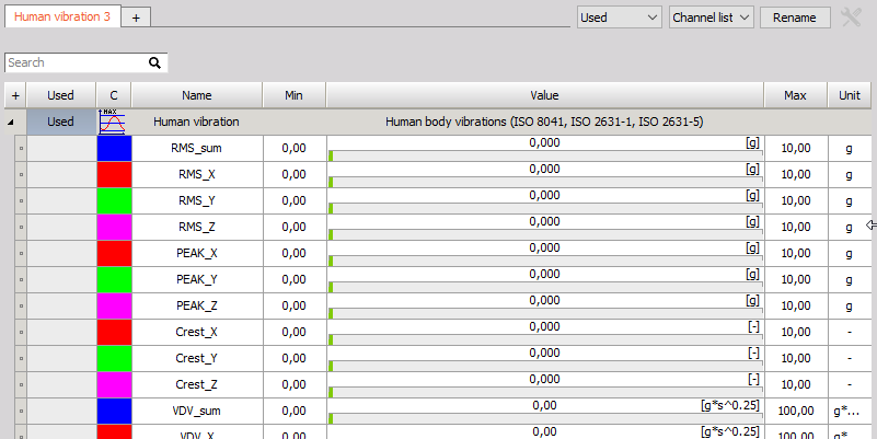
The RMS, MSDV, VDV and MTVV are calculated for sum of all three axes, therefore a value for output channel is created.
RMS output channels
- For selected Overall values in Calculated parameters section:

- For selected Interval logging in Calculated parameters section:

VDV output channels
- For selected Overall values in Calculated parameters section:

- For selected Interval logging in Calculated parameters section:

MSDV output channels
- For selected Overall values in Calculated parameters section:

- For selected Interval logging in Calculated parameters section:

MTVV output channels
- For selected Overall values in Calculated parameters section:

- For selected Interval logging in Calculated parameters section:

NOTE: When creating output channels for above-listed Output channels option Overall values and/or Interval logging in Calculated parameters section must be selected.
Weighted raw ouput channels
- Independently of selection in Calculated parameters section:

al (ISO 2631-5) output channels
- Independently of selection in Calculated parameters section:

D (ISO 2631-5) output channels
- None of choices is selected in Calculated parameters section:
- For selected Overall values in Calculated parameters section:

- For selected Interval logging in Calculated parameters section:

NOTE: When Overall values or Interval logging are selected, the acceleration dose will only be calculated in the Z direction (Dz channel).
Channel list view
If we open Channel list the following output channels (if filters selected) will appear:
For help with Output Channel list see -> Setup -> Output Channel list.
Calibration
The triaxial accelerometer can be calibrated in two ways.
1. Scaling with calibration certificate
If we don’t use the calibrator, but have the sensitivity of triaxial accelerometer, we can define it directly in the channel setup using the values from the triaxial accelerometer calibration sheet. This can be done from Dewesoft Setup -> Analog in tab Channel setup for the Human vibration Application module used channels.
For information about Calibration analog input channel see -> Calibrate.
NOTE: First, as usual, we enter the ‘Units of measurement’. We have a sensitivity of the sensor expressed either in mV / m/s2 or mV/g (or both) for IEPE sensors and in pC/g for piezoelectric (charge) sensors. Therefore we need to scale it to physical quantity. The Reference sensitivity is the key value to enter in the Dewesoft setup. Then it is best to go to scaling ‘by function’ tab, check the Sensitivity and then enter value from calibration data sheet. We need to change also the amplifier range to best fit the current acceleration values and the filter to fit the sampling rate. If Sirius is used, the filter can be set to the highest values (because amplifiers A/D converter provides sharp anti aliasing filters) unless we intentionally want to have lower frequency range.
2. Calibrating the triaxial accelerometer with calibrator
If we want to perform calibration with the calibrator, we can perform it here - in Human vibration module itself. First enter the Reference value of vibration. This can be read from the calibrator.
NOTE: Usually the calibration levels are 10 m/s2 peak, which is 7,07 m/s2 RMS or 0,72 g. We need to enter this value in Reference value field.
As soon as we mount the sensor on the calibrator, we should see the amplitude and the frequency of the signals. In this case we see that we applied the sensor in Z direction.
The frequency of calibration is below 200 Hz (80 or 160 is typical, in our case it is 80 Hz). This is a simple check that everything is OK.
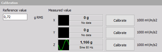
Next simple step is to press the Calibrate button near the axis which is currently calibrated. As soon as we do this, we will see sensor sensitivity in mV/g which can be checked against the sensor calibration certificate. Little percent difference is acceptable.
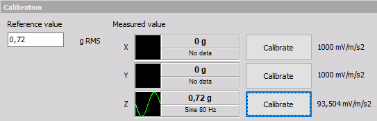
Then we can see the calibrated live RMS value of the vibration (in example above 0,72 g).
NOTE: We need to use setup sample rate in Dewesoft at least 5 kHz or higher to make successful accelerometer calibration. This can be changed in Dewesoft Analog in.