Power quality
Harmonics calculation
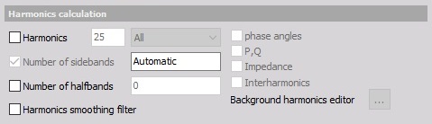
Harmonics
The line voltage isn’t perfect and can have distortions, which are nicely shown as harmonics in the frequency spectrum.
When the Harmonics option is checked, like in sample, we can:
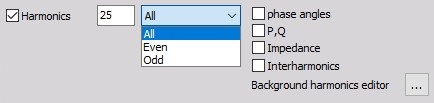
- define number of harmonics (with enter value in this field)
- select All or only Even or Odd harmonics from drop down list
- select additional harmonics option: phase angles, P,Q, Impedance, Interharmonics.
Background harmonics
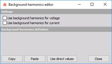
On upper picture you can see additional button, which appeared by checking Harmonics option.

The background harmonics are used to compensate normal load and to see the difference from this normal conditions.
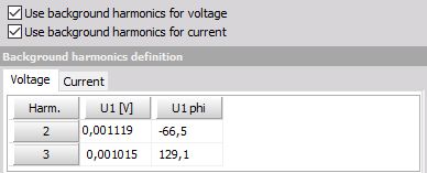
When we open the editor two options can be selected to use and define background harmonics:
- Use background harmonics for voltage
- Use background harmonics for currect
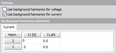
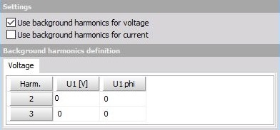
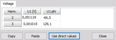
When one from this options (or both) is checked, table with voltage (U1 in V unit and U1 phi - phase angle) / current values (I1 in A unit and I1 phi - phase angle) for defined number - 1 background harmonics appear.
In example above we have selected 3 harmonics, therefore voltage / current value for second and 3rd harmonics can be defined.
Table Voltage / current values can be defined with:
- selecting cell and enter value
- Copy and Paste function
- selecting Use direct values button to enter current value in table cells
When both options for background harmonics are checked, table with current values appear in separate tab.
Other harmonic calculations
In Harmonics calculation we can make additional calculations like:
- Number of sidebands - The basic idea of sidebands is that a certain frequency range is considered as one harmonic.
- Number of halfbands - The IEC 61000-4-7 requires for the grouping of the harmonics sidebands where only the square root of the quadratic half of them should be added. This is required for the lowest and highest line and is defined as halfbands in Dewesoft.
- Harmonics smoothing filter - This options enables the low-pass filter which is required in IEC 61000-4-7 standard.
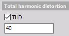
Total harmonic distortion
We can calculate THD = total harmonic distortion (sum of all harmonic values).
To create THD output channels this option must be checked. In field on right value the number of harmonics for THD can be entered (40 = default).
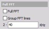
Full FFT
This options calculates the Full FFT which can be exported to the database and displayed via a 2Dgraph.
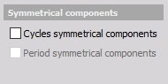
Symmetrical components
Symmetrical components are available only on three phase systems and tell us the unbalance of the grid.
Rapid voltage change
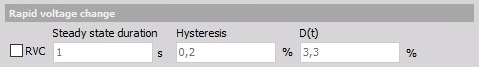
The Rapid Voltage Changes are parameters which are added as a supplement to the flicker standard. Rapid Voltage Changes describe all voltage changes which are changing the voltage for more than 3% at a certain time interval. These voltage changes can afterward’s be analyzed with different parameters (depth of voltage change, duration, steady state deviation, etc.).
Voltage flicker and Flicker emission
The flicker is actually power quality parameters measuring low frequency distortions of the voltage.
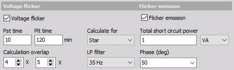
For this option we can set:
- Pst time - Short calculation time interval, defined in minutes
- Plt time - Long calculation time interval, defined in minutes
- Calculation overlap - multiplier of calculation overlap for Pst time and Plt time; with up arrow beside value field we can increase and with down arrow we can decrease multiplier value
- Calculate for - from drop down list we can select type of calculation - for Star or Delta or Both:
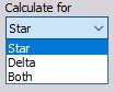
This function is only available if calculations Calculate line voltage and Calculate waveforms in Power / Star-Delta calculations are used!
- LP filter - 6 th order low pass Butterworth filter’s cutoff frequency is auto selected according to standard, or manually selectable (35 Hz or 42 Hz)
Flicker emission calculates the influence of the current on the flicker (contribution of the device being measured on the flicker).
We need to enter impedance in Ohm and Phase as two additional parameters for calculation.