Brake Noise
Brake noise plugin is used for detecting and tracking noise caused by mechanical vibration in various braking systems using an algorithm that is based on the VDA 303 guideline.
The detection of brake noise is based on the comparison of sound and the mechanical vibration amplitude spectrum. The only inputs needed to detect brake noise events are sound and vibration measurements. The amplitude spectrum calculation with a fast Fourier transform (FFT) algorithm is completely integrated into the plugin. During the measurement, the plugin can detect and track multiple brake noise events in multiple sound-vibration detection pairs simultaneously, while statistical parameters of the noise event, or of any scalar Dewesoft channel, can be calculated during an actual brake noise event.
Brake noise plugin is flexible regarding different hardware configurations. With an automatic pairing of defined sound and vibration inputs in detection pairs, the configuration workload is significantly reduced for large measurement setups. The amount of brake systems measured and analyzed is only limited by the available computer resources.
As with Dewesoft’s math modules, Brake noise plugin can also be used in analysis mode to recalculate the data and correct initial setup mistakes.
Setup
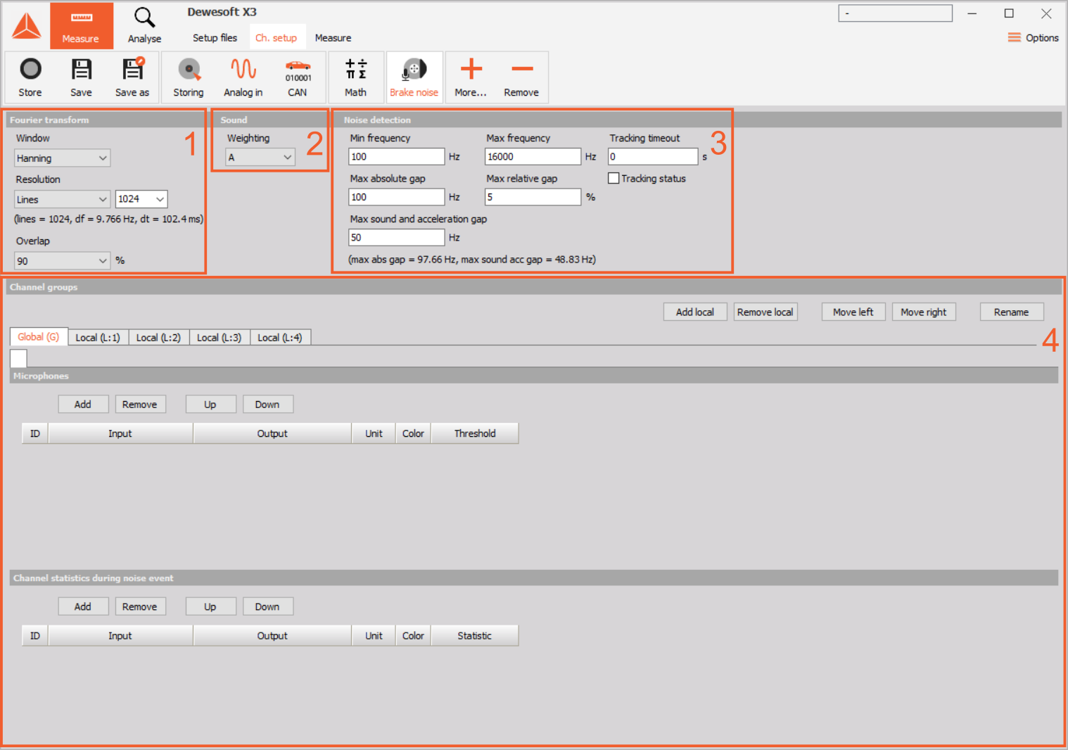
Brake noise plugin can be setup by it’s user interface in channel setup. Plugin’s user interface can be divided in four major parts:
By setting up the plugin you get output channels in which results are written. The range of results and how are they generated from detection pairs has its own topic:
User interface type
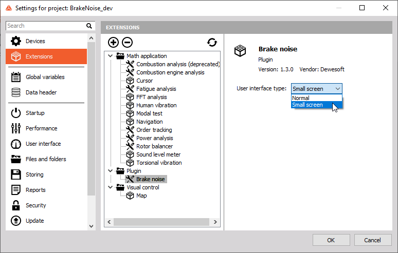
If all of the user interface items can not be displayed on your screen, there is an option to switch the user interface type to the one adapted for small screens. The switch is available in Dewesoft settings: Settings/Extension/Plugin/Brake noise.
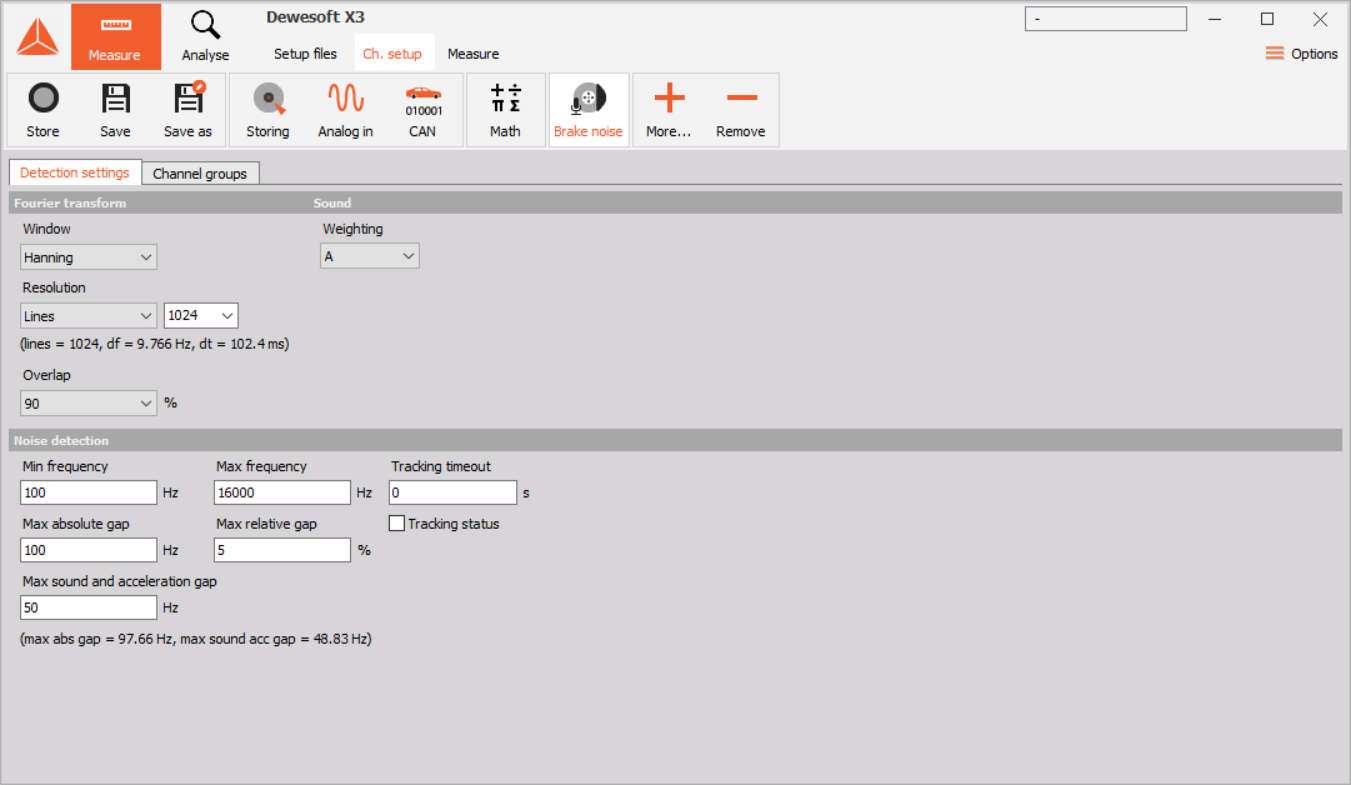
With the user interface type option set to Small screen settings are divided into two tabs:
- Detection settings tab contains Fourier transformation, Sound weighting and Noise detection settings,
- Channel groups tab contains Channel groups settings.
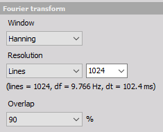
Fourier transformation settings
To detect brake noise caused by vibration, plugin compares amplitude spectrums of sound and mechanical vibration measurements. The transformation from time signal to frequency spectrum is calculated in the plugin. Therefore the only inputs needed for brake noise detection are sound pressure signal in pascals and mechanical vibration signal which is usually measured with an accelerometer. Amplitude spectrum of the measured signals is calculated with the fast Fourier transform algorithm (FFT). The algorithm used is the same as in other Dewesoft components that calculate signal frequency spectrum like Fast Fourier Transform. The settings exposed in the plugin are those that are relevant to brake noise detection. The default settings are based VDA 303 guideline.
- Window: here you can select which window is applied to the signal before amplitude spectrum calculation. You can select from one of this windows: Rectangle, Hanning, Hamming, Flat top, Triangle, Blackman, Blackman-Harris. By default Hanning window is selected.
Resolution: here you can select the amount of samples that are used in the transformation. This determines the number of lines calculated by the transform, line resolution and duration of the signal that is used for the transformation. Resolution can be specified in three different ways:
- Lines: the number of lines of the frequency spectrum calculated,
- Delta frequency: frequency resolution in Hz of calculated spectrum,
- Duration: the duration of the signal in milliseconds that is taken into the transformation.
In every option you can select one of the values that are already defined or you can input the desired value. The label below resolution combo boxes shows the actual values of lines, delta frequency and duration of the transformation. In case of specified delta frequency or duration the exact values specified usually cannot be achieved. This is determined mostly by the acquisition sample rate selected. The actual FFT that will be used in calculations will be as close as possible to the specified value. Also in case of duration or delta frequency the actual FFT size and number of lines does change if Dewesoft acquisition sample rate changes. In case of lines as the resolution input option, the size of FFT will remain the same if Dewesoft acquisition sample rate changes. But the resolution in terms of actual delta frequency and duration will change. The default setting of resolution option is lines, with 1024 lines calculated by the transformation. With acquisition sample rate set to 50 kHz FFT fulfills the requirement of being able to detect brake noises with duration of at least 45 ms.
Overlap: to correctly capture noise events amplitude spectrums have to be calculated with an overlap. The percent of overlap determines the amount of newest samples from the previously calculated FFT that are going to be used also for the new FFT calculation. You can select 50, 66, 75 or 90 percent overlap. By default 90 percent overlap is selected, this ensures that the calculation will at worst capture noise events that are as long as the duration of the signal used in the FFT calculation.
Sound weighting
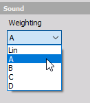
The sound amplitude spectrum is always calculated in decibels and frequency weighted according to the selected weighting setting. Weightings that you can select are: Linear (no weighting), A, B, C and D. By default A weighting is selected.
Noise detection
Brake noise event detection and tracking works by comparing the amplitude spectrum of sound and vibration signals. Amplitude peaks from both spectrums have to be above a threshold that is specified for each sound and vibration channel on it’s own. Amplitude peaks that are above the threshold are then checked in the detection algorithm.
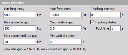
Detection algorithm can be setup with the edit boxes:
- Minimum frequency and Maximum frequency: the detection algorithm will only compare amplitude peaks which are in the range between minimum and maximum frequency set here. By default minimum frequency is set to 100 Hz and maximum to 16000 Hz.
- Maximum absolute gap: this determines if two or more amplitude peaks belong to the same noise event or should they be treated as different noise events. Therefore if the difference in frequency of peaks is less than the maximum absolute gap defined here the the algorithm threats this as one noise event. In statistics involving amplitude peak calculations only the peak with maximum value is used. By default maximum absolute gap is set to 100 Hz.
- Maximum relative gap: has the same functionality as maximum absolute gap. However the frequency difference between peaks that determine if they belong to the same noise event is calculated as a percent of frequency at which this peaks are. For example if relative gap is set to 10 percent and there is one peak at 1000 Hz and one at 1040 Hz the absolute gap determined from the maximum relative gap is calculated as 1000 Hz * (5% / 100%) = 50 Hz. Because the difference between peaks is 1040 Hz - 1000 Hz = 40 Hz which is less than 50 Hz these two peaks are treated as coming from a single noise event. By default maximum relative gap is set to 5%.
- Maximum sound and acceleration gap: this setting is crucial to match sound and vibration amplitude peaks. It determines if the sound amplitude peak is actually related to any peak in the vibration amplitude spectrum. If the difference in frequency between the sound and vibration amplitude peak is less than the one defined here sound peak is caused by mechanical vibration. By default maximum sound and acceleration gap is set to 50 Hz.
- Minimal valid duration [s]: short noise events that are not really important for measurement because they are undetectable by the human ear, can be rejected for certain periods that are defined as minimal valid duration.
The label at the bottom shows an exact value of maximum absolute gap and maximum sound and acceleration gap according to the FFT resolution. Usually the exact values can not be met. In that case gaps are rounded down to the closest possible gap. This is also true when an absolute gap is calculated from maximum relative gap setting. This ensures that the settings are always respected.
Tracking timeout
Brake noise events are often unstable. In that case the amplitudes of vibration and noise during the noise event can go below amplitude thresholds for short periods of time. Without tracking timeout brake noise detection algorithm will stop with the tracking of that particular event when it can not detect it. At stop of detection the results of event statistics are going to be written out. When the same event reappears it is going to be treated as a new noise event. This usually isn’t desirable. Therefore an additional tracking timeout can be set. When tracking timeout is above zero the detection algoritm will wait for a set amount of time for each noise event to reappear. If the same noise event reappears in the time set, it is going to be tracked as the same noise event. It is important to note, that when amplitudes of an event are below threshold the statistics of an event won’t be updated. However the duration output of an event is going to take into an account also the time between periods of event disappearance if that period is followed by event reappearance.
Tracking status
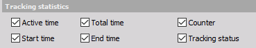
Plugin detection state can be observed by checking the Tracking status checkbox:
![]()
When activated plugin will output an additional channel called Tracking status. Also an additional edit box for tracking status Post time will appear. The channel will output a value of Not tracking (value: 0) or Tracking (value: 1). The value Not tracking will be output if the plugin hasn’t detected any brake noise event in any detection pair for at least the time specified in the post time editbox. Otherwise the value in the channel will be set to Tracking. The main purpose of this channel is for the use with triggered storing when brake noise is detected. Tracking status post time is used to ignore the small gaps in tracking when the noise event is fading out. When using tracking status as a store trigger it is important to also store enough data for possible recalculation in analysis mode. Therefore you have to set enough storing trigger pre time to fit the duration of the FFT. It is important to know that tracking status post time has no relation to the storing trigger post time.
Channel groups
When investigating noise caused by mechanical vibration, the detection is based on detection pairs composed of one sound and one vibration measurement. This is an input to the detection and tracking algorithm. To investigate the type of noise and what is causing it plugin also offers statistic calculations that are calculated for the duration of each noise event. Because different noise events can occur at the same time: simultaneous detection, tracking and statistic calculations are fully supported. With multiple measurements of sound and vibration the definition of all the pairs and related statistics would get time consuming and error prone. The aim of defining detection channels and statistics in channel groups is to reduce the workload. This is done by generating the detection pairs with statistic calculations automatically.
When measuring brake noise usually there are channels that are relevant for the whole vehicle (cabin microphone, vehicle velocity, environment temperature…) and channels that are only related to a specific brake system (brake pad vibration, disc temperature, brake pressure…). Input channel and statistic definitions are separated into one global group and multiple local groups. In the user interface each channel group has it’s own tab. The first tab is always reserved for the global group and cannot be removed.
Global group
In the global group you can define sound signal inputs and channel statistics which are relevant for an investigation of noise events on all of the measured braking systems.
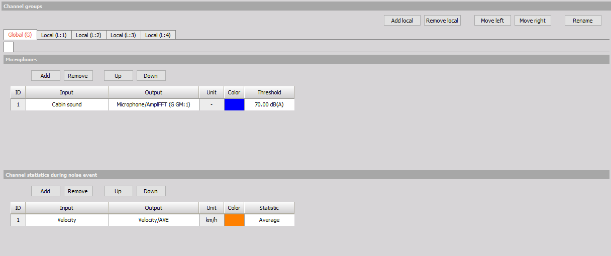
In the above picture you can see the user interface of the global channel group. It is separated in two parts:
- Microphones: this contains an input grid for global microphones. Here you can define sound input channels which are going to be used to investigate the noise events on all local groups. Usually signals from cabin microphones are input here. For every microphone you can define the threshold in decibels. Only sound amplitudes above this threshold are going to be regarded as brake noise events in the detection algorithm. It is important to know that sound pressure measurement signals selected in the grid have to be measured in pascals. Only synchronous channels without sample rate divider are supported.
- Channel statistics during squeal: here you can define the statistic calculation that is going to be calculated during any brake noise event detected in any detection pair. You can select any scalar Dewesoft channel as an input. The statistic calculations that are available are: Average, Minimum, Maximum and Delta.
Local groups
Here you can define the vibration, sound measurements and statistics that are related to the specific brake assembly. The number of local groups is variable, you can add, remove or rearange their order. This can be done with the four buttons on the top left of the channel group user interface:

By default four local groups are already added in the plugin (one for each wheel brake assembly). The settings of a local group are divided by two tabs:
Accelerometers and microphones
In this tab you can define the inputs that measure vibration of the components and microphones that are going to be used to detect noise events only with vibration inputs of this group.
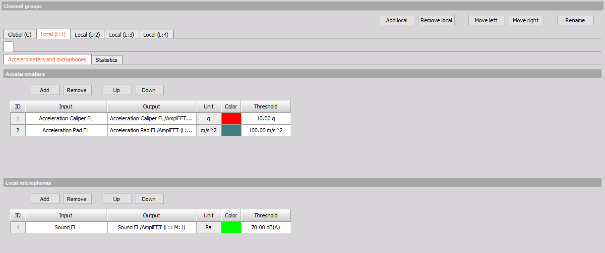
- Accelerometers: here you can define the vibration measurement channels used for detection of brake noise. Usually vibrations are measured with an accelerometer but also other sensors with high enough bandwidth can be used. For every input you can define a threshold. Only the amplitudes above this threshold are going to be regarded as high enough vibrations that could cause the noise. The unit of the input signal isn’t important, threshold is always defined in the same unit as the input signal. Only synchronous channels without sample rate divider are supported as an input.
- Microphones: similar to microphone input grid in the global group here you can define sound input channels. The difference is that these will only be used to detect noise with vibration inputs of the same local group. For every microphone you can define the threshold in decibels. Only sound amplitudes above this threshold are going to be regarded as brake noise events in the detection algorithm. It is important to know that sound pressure measurement signals selected in the grid have to be measured in Pascals. Only synchronous channels without sample rate divider are supported as an input.
Statistics
In the statistics tab you can pick the noise event statistics that you want to be calculated ar add a channel statistic that is going to be calculated only in detection pairs of this group.
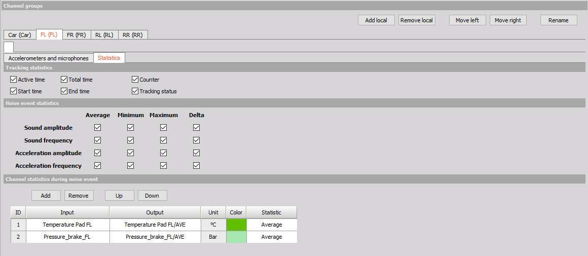
- Tracking statistics:
- Active time: is calculating active time of event duration. It is calculated only when values are above a certain threshold of minimum valid duration [s].
- Total time: is calculating total time of an event duration.
- Start time: will output the start time of a valid noise event.
- End time: will output the end time of a valid noise event.
- Counter: will count valid noise events for each statistic acc-mic pair where it is applied.
- Tracking status: each detection pair has its own tracking status, and it’s possible to read if the event is detected on a detection pair of interest.
Noise event statistics: here you can pick various statistics of the brake noise event to be calculated. In the top table of checkboxes you can activate the calculation of: Average, Minimum, Maximum and Delta values of Sound amplitude, Sound frequency, Acceleration amplitude and Acceleration frequency. In the bottom line you can activate the output of noise event Duration, Start time, End time and Counter. Counter will output the consecutive number of brake noise event detected at a specific detection pair.
Channel statistics: here you can define the statistic calculation that is going to be calculated during any brake noise event detected in the detection pair defined by the local group. You can select any scalar Dewesoft channel as an input. The statistic calculations that are available are: Average, Minimum, Maximum and Delta.
Outputs
Results of plugin calculations are written in the outputs. There are three different types of outputs:
- Amplitude spectrums: result of amplitude spectrum calculation of each microphone and accelerometer is written in an asynchronous array channel,
- Statistic outputs: the statistic calculations on each microphone-accelerometer detection pair are going to have it own outputs. In it the results of statistic calculations are going to be written each time the noise event was finished. Statistic result is always output in asynchronous scalar channel.
- Tracking status: only one tracking status can be output by the plugin. It outputs the state of the tracking algorithm according to Tracking status.
Since Tracking status is straightforward and only requires one setting to activate here we are going to focus on Amplitude spectrum and Statistic outputs and how are they related to the setup. In the following image we have an example of the setup with two local groups.
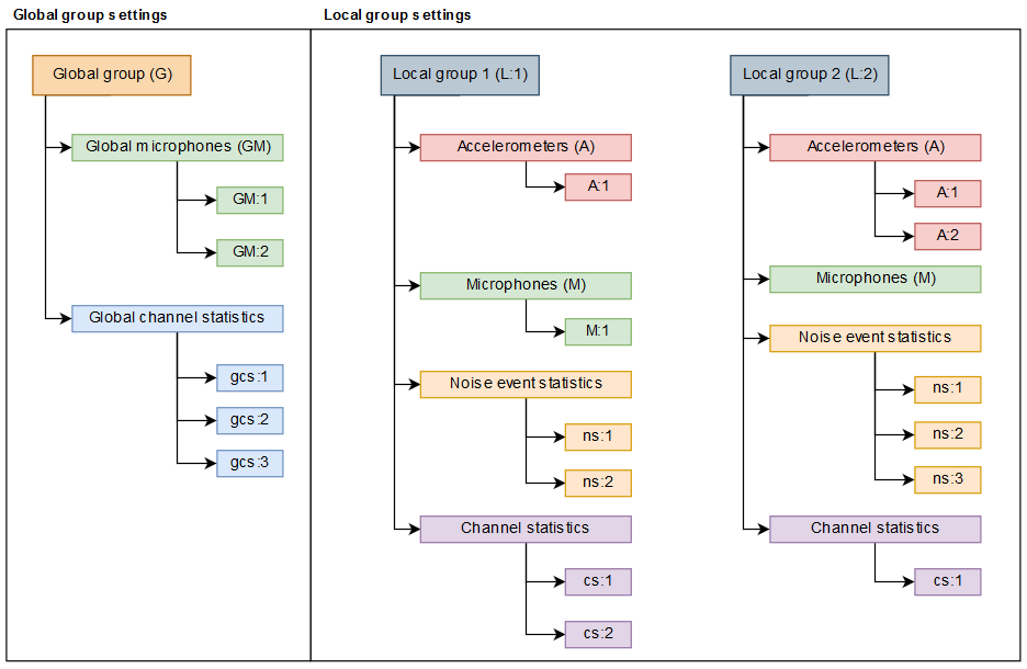
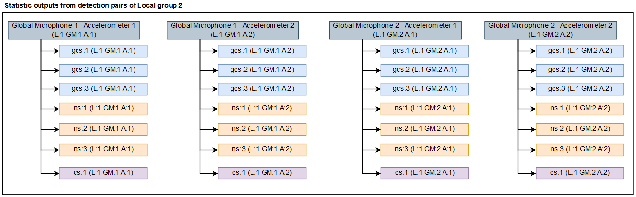
In the global group there are two global microphones (GM:1, GM:2) and three global channel statistics (gcs:1, gcs:2, gcs:3). In local group 1 there is one accelerometer (A:1) and one local microphone (M:1), two noise event statistics (ns:1, ns:2) and two channel statistics (cs:1, cs:2). In the local group 2 there are two accelerometers (A:1, A:2), no local microphones, three squeal statistics (ns:1, ns:2, ns:3) and one channel statistic (cs:1).
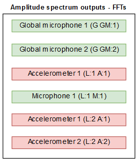
From each microphone and accelerometer an amplitude spectrum output is generated.
Each accelerometer forms detection pairs with global and local microphones defined in the same group as the accelerometer. Each detection pair from a local group accelerometer has statistic calculations which are composed of: global channel statistics, local squeal statistic and local channel statistic. Each statistic calculation has its own output. In the presented setup there are seven detection pairs. In local group 1 the accelerometer (A:1) forms detection pairs with two global microphones (GM:1, GM:2) and one local microphone (M:1). In each detection pairs three global channel statistics (gcs:1, gcs:2, gcs:3), two noise event statistics (ns:1, ns:2) and two channel statistics (cs:1, cs:2) are calculated.
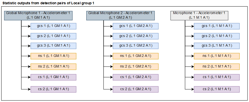
In local group 1 the accelerometers (A:1, A:2) form detection pairs with two global microphones (GM:1, GM:2). In each detection pairs three global channel statistics (gcs:1, gcs:2, gcs:3), three noise event statistics (ns:1, ns:2, ns:3) and one channel statistic (cs:1) are calculated.
Numbering
The numberings of the outputs are automatically added to the outputs. All of the numberings are related to the position of of the group, microphone and accelerometer in the user interface. The automatic numbering and naming will stop if the output name is manually changed to a different value than the automatically assigned value. The abbreviations of microphones and accelerometers are fixed: GM for global microphones, M for local microphones and A for accelerometers. The abbreviations of groups can be changed. This is done in the rename dialog that opens for the selected channel group when pressing the Rename button in the Channel group user interface. In channel selector outputs are organized according to channel groups and detection pairs that they belong to.
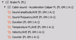
In the above image we can see the statistic outputs of a pair that comes from local group named Brake FL with an abbreviation FL. The pair is formed between a global microphone channel Cabin sound and accelerometer channel Acceleration FL.