Theory of balancing
Balanced rotors are essential for most kinds of rotating machinery. Unbalance will create high vibrations causing material defects and reducing the lifetime of a material. In most cases the rotor unbalance is the major problem of vibration, it is related to the first order (= rotational frequency).
We assume, that we consider the so-called “rigid rotors”, which is true for nearly all practical cases. That means the operating speed of the machine is below 70% of its first resonance frequency. The resonance frequency is the critical speed, where structural resonances cause heavy vibrations. At the resonance, the phase is turning quickly and it would be impossible to make a correct measurement.
NOTE: The requirement in terms of sampling rate depends on the first order (e.g. 3000 RPM/60 = 50 Hz → required sampling rate ≥ 3520 Hz). Also, a precise vibration sensor signal is mandatory
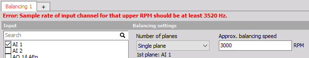
NOTE: The minimum sample rate is calculated from the balancing speed RPM (Max RPM + 10%) and the maximum order that is selected in the settings (32 is default). (3000RPM / 60) * 1.1 * 2 * 32 = 3520 Hz.
The goal of balancing is to minimize vibrations related to the first order. Basically, it works like this: We measure the initial state, then we add a trial weight of known mass, calculate the position and mass of a counterweight, remove the trial weight and put the calculated weight on the opposite side, to cancel out the imbalance.
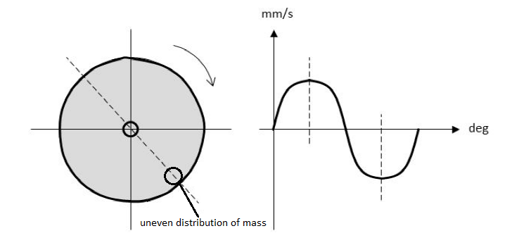
When an unbalance exists, the first order (rotational frequency) can be seen clearly. As shown in the example below, on the rotor exists an uneven distribution of mass.
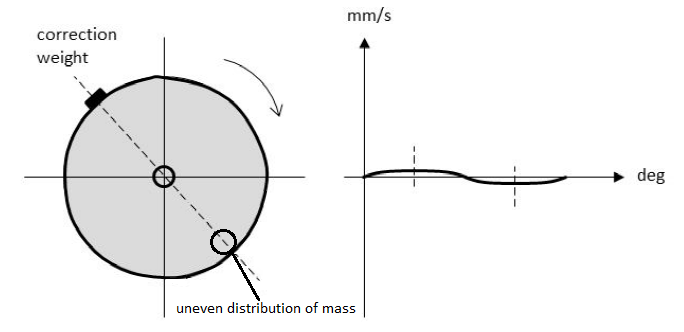
A correction weight is added (or material is removed) on the opposite side, which cancels out the major part. This procedure can then be repeated until satisfaction.
Single and dual plane balancing
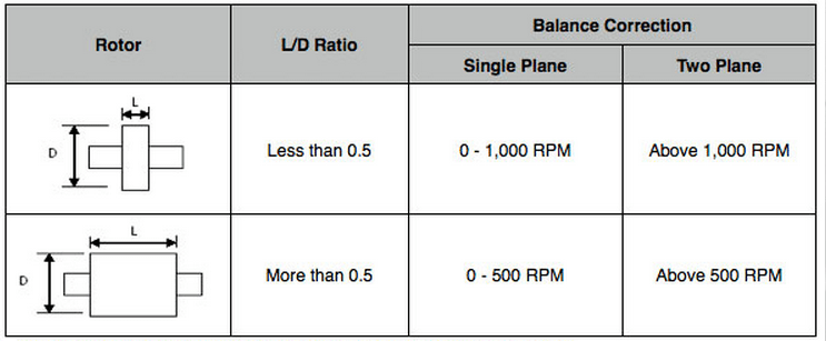
Depending on the machinery, single or dual plane balancing is used. Selecting one plane or two plane balancing generally depends on two factors. One of the factors is the ratio of the length of the rotor (L) to the diameter of the rotor (D). The other factor is the operating speed of the rotor. As a general rule of thumb, we can refer to the table shown below.
The procedure for a single plane or dual plane balancing will be different, depending on which option is chosen. But basically the following steps have to be taken:
- initial run
- trial run
- correction run(s)
Step-by-step procedure
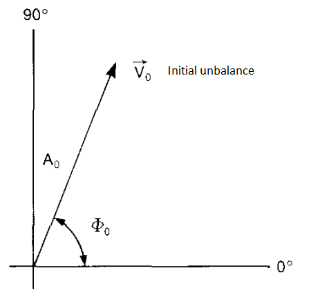
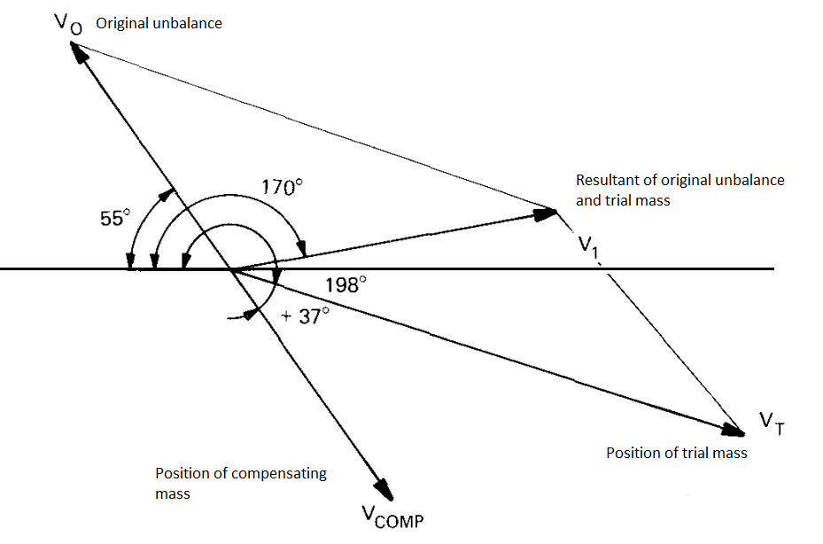
The first step of balancing procedure is to do an initial run. The machine has to be run up the operating speed. The vibration velocity is detected. The velocity level and phase angle give together a vector that represents the original unbalance of the rotor. The length of the vector is equal to the vibration amplitude and its direction is given by the phase angle.
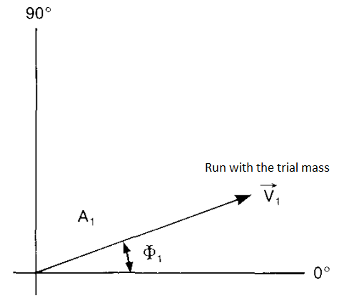
The second step is to add a trial mass. A trial mass has a known weight and it is fixed at a known radius at an arbitrary angular position on the rotor. The machine is again run up to operational speed. We get a new vibration velocity level and a new phase angle. These values represent the resultant effect of the initial unbalance and the trial mass.
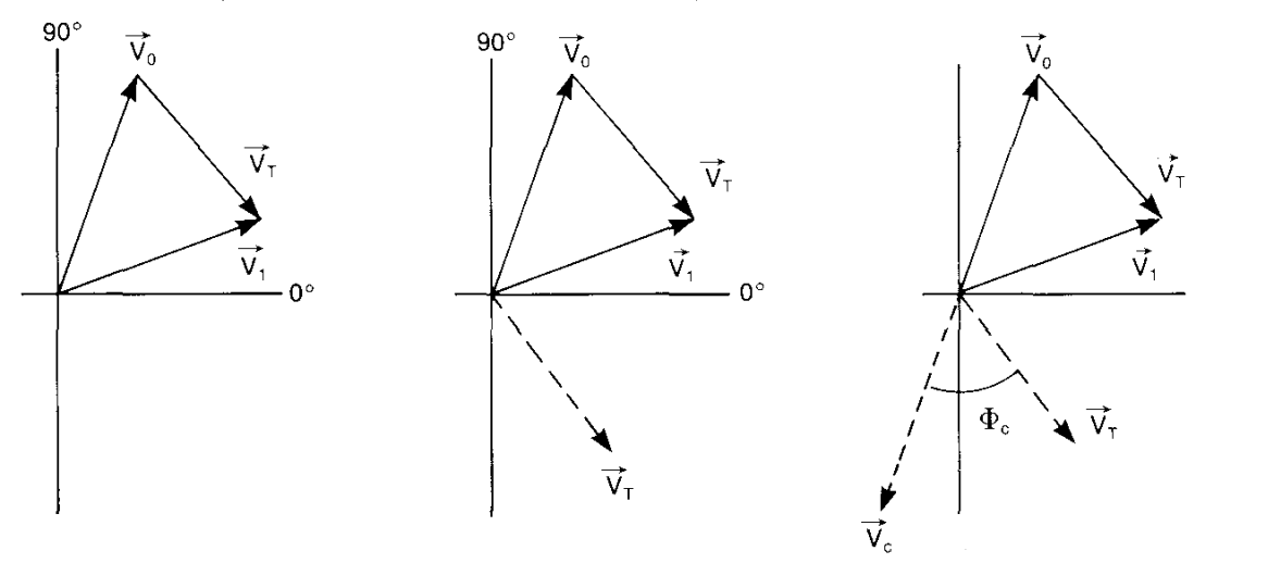
The tips of vectors $V_0$ and $V_1$ are joined by means of the third vector $V_T$, which is marked so that it indicates the $V_0$ to $V_1$ direction. This vector represents the effect of the trial mass alone. A vector is drawn parallel to the vector $V_T$, with the same amplitude and direction, but starting at the origin.
In the opposite direction to $V_0$, there is a vector $V_C$ and it represents the position and magnitude of the mass required to counteract the original unbalance.
If we assume that the amplitude of the vibration is proportional to the unbalance mass, we get the expression that enables us to find the value of compensating mass ($M_{\text{COMP}}$).
$$ \frac{M_\text{T}}{\vec{v_\text{T}}} = \frac{M_{\text{COMP}}}{\overrightarrow{v_{\text{COMP}}}} = \frac{M_0}{\vec{v_0}} $$
$$ M_{\text{COMP}} = M_0 = \frac{\vec{v_0}}{\vec{v_T}} \cdot M_T $$
The position of the mass relative to the position of the trial mass can be determined from the vector diagram.
Now we have sufficient information for the vector diagram with vector lengths proportional to the measured vibration velocity levels.
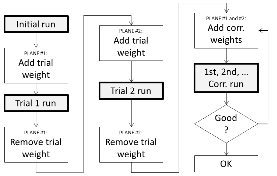
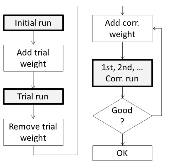
The procedure in DEWESoft is guided by the visual control instrument. The flowcharts below show the routines for single and dual plane balancing. Instead of adding correction weights you can also remove material from the opposite position (angle + 180°).
Single plane balancing procedure
Dual plane balancing procedure
By adding the correction weights for both planes at the same time, we save one additional step.