Device and software setup
Device Network setup
In order to recognize Velodyne LIDAR sensor inside DewesoftX, the ethernet network setup needs to be done. Velodyne LIDAR sensor IP address is factory set on default value 192.168.1.201. The following procedure prepares a computer to communicate directly with the sensor at that address.
If using the computer’s main Ethernet port, disconnect it from whatever network it’s on. If using a secondaryEthernet interface, the primary network cannot be a 192.168.1 network. If it is, use the primaryEthernet interface instead.
- Open the computer’s Network COnnections page.
- Open the applicable Ethernet adapter and make sure the interface is enabled.
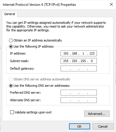
- Open Properties -> Internet Protocol Version 4 (TCP/IPv4). *Enable ‘Use the following IP address:’ function.
- Write in an IP address for the Ethernet port: 192.168.1.XXX
- ‘XXX’ may be any integer from 2 to 254, except 201 (which is the LIDAR’s IP)
- ‘XXX’ may be any integer from 2 to 254, except 201 (which is the LIDAR’s IP)
Add Device into DewesoftX
After configuring LIDAR sensor’s network, open DewesoftX, go to settings, and add Velodyne LIDAR as a Device:
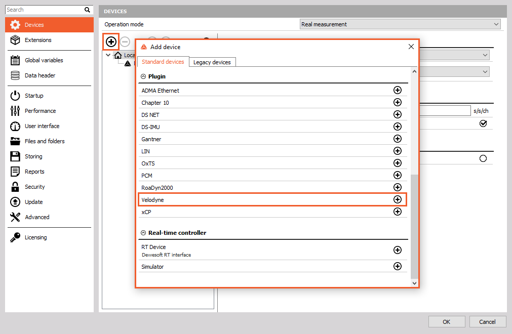
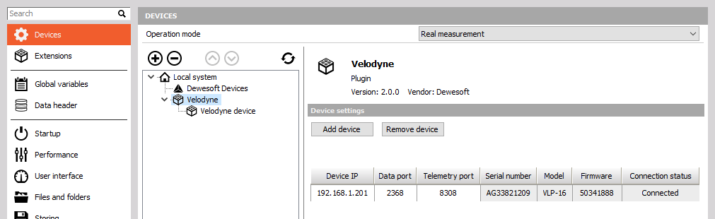
Click on Velodyne tab, click on Add device button, and type in the Velodyne LIDAR sensor’s IP:
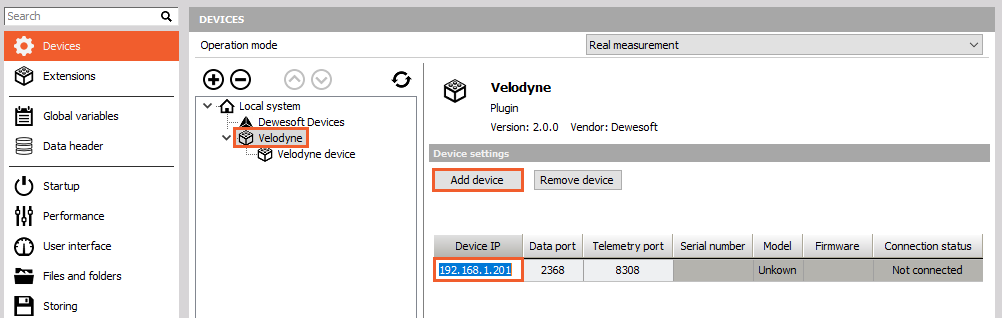
The Connection status on the right side of the device’s IP should turn to status Connected. Connected status indicates recognized and connected LIDAR device:
Apply settings with OK, and now redirect to DewesoftX’s Channel setup tab, where the Velodyne module icon will be previewed:
Setup the Velodyne LIDAR module
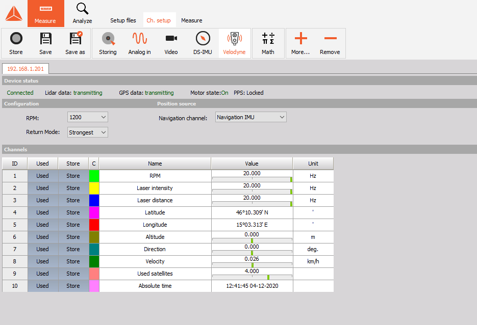
There are a few settings that can be set in Velodyne LIDAR module. The image above is the only User interface of the Velodyne plugin.
Device status
Device status bar is an indicator of LIDAR sensor’s connection and recognition.
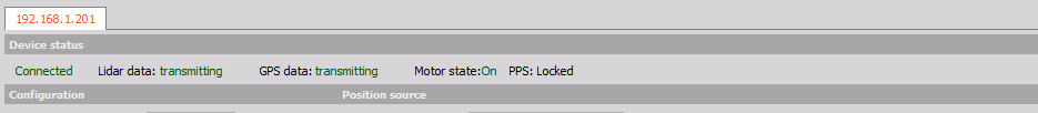 * Device status can be:
* connected or,
* disconnected (check on Velodyne in DewesoftX settings).
* Lidar data:
* transmitting,
* not transmitting (check the LIDAR device).
* GPS data:
* transmitting,
* not transmitting (check the connection between LIDAR and GNSS device, or check the GNSS device’s channels - navigational channel)
* Motor state:
* On - LIDAR is rotating,
* Off - LIDAR is not rotating.
* PPS:
* Locked - GPS PPS is connected
* Synchronizing - GPS PPS is connecting
* Absent - GPS PPS is not connected or present
* Device status can be:
* connected or,
* disconnected (check on Velodyne in DewesoftX settings).
* Lidar data:
* transmitting,
* not transmitting (check the LIDAR device).
* GPS data:
* transmitting,
* not transmitting (check the connection between LIDAR and GNSS device, or check the GNSS device’s channels - navigational channel)
* Motor state:
* On - LIDAR is rotating,
* Off - LIDAR is not rotating.
* PPS:
* Locked - GPS PPS is connected
* Synchronizing - GPS PPS is connecting
* Absent - GPS PPS is not connected or present
Configuration and Position source
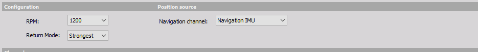
- RPM - select the rotational speed of the Velodyne LIDAR sensor
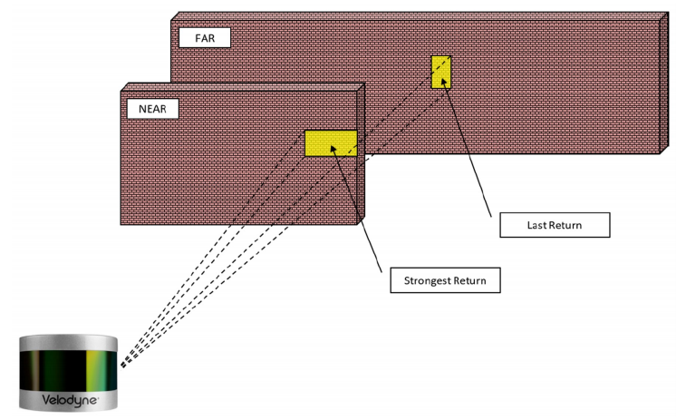
- Return mode - defines the return of the laser pulses for the LIDAR sensor.
- Strongest
- Last
- Navigational channel - the navigational channel usually from GNSS device have to be selected. Navigational channel consists of lattitude, longitude and heading.
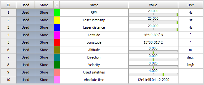
Channels
Channels represent the outut values from Velodyne LIDAR module. With click on Unused you can enable them, and with click on Used you can disable them. The image below represents all the Used channels, which will be calculated and previewed later in Measure mode.
For more check on Output sections of the Velodyne LIDAR manual.