Engine Settings
NOTE: Besides the following instructions, you have a detailed explanation of setting up the Engine on our web page Combustion Engine Analyzer.
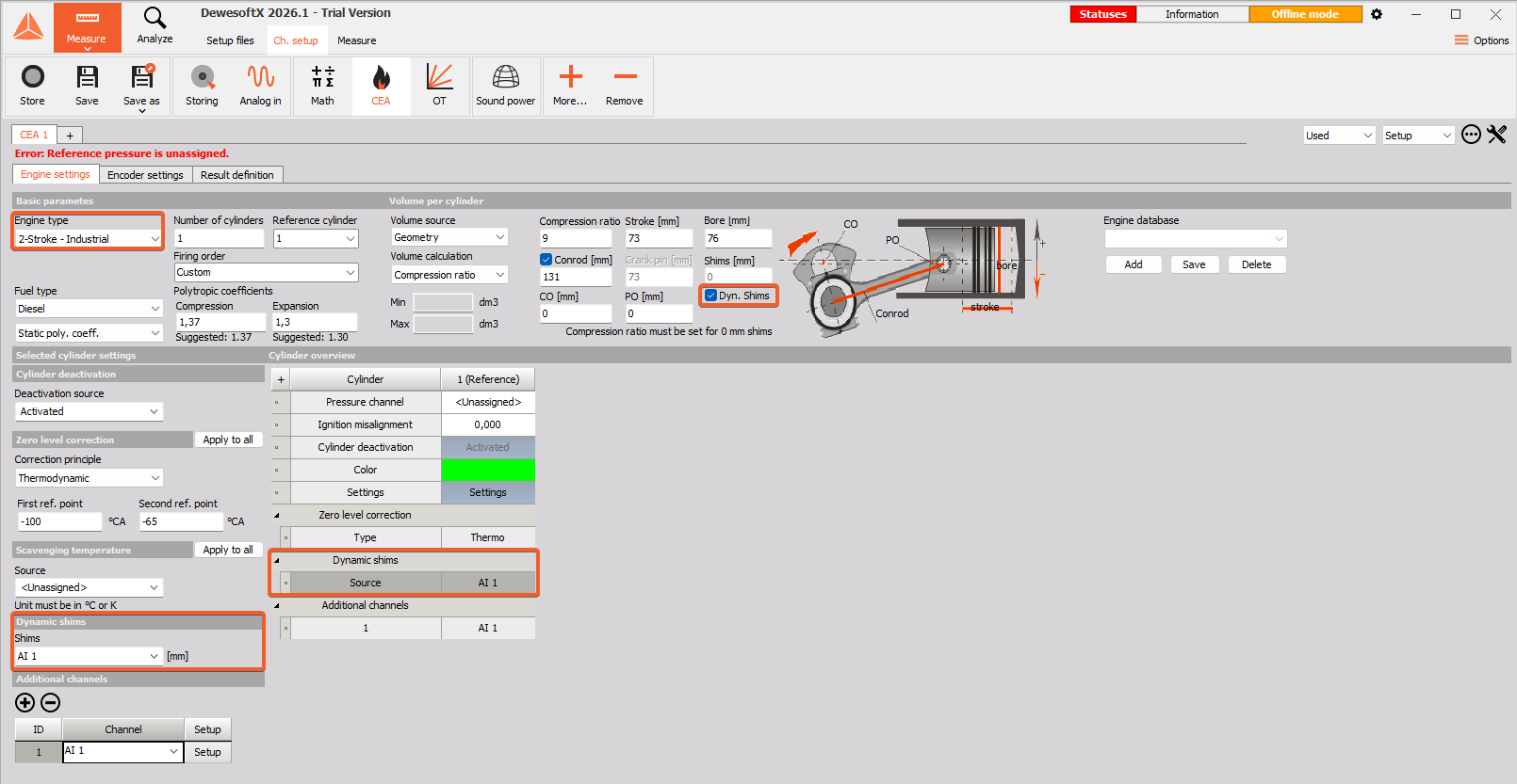
After selecting Engine type CEA or after new CEA module is added following setup screen is displayed:
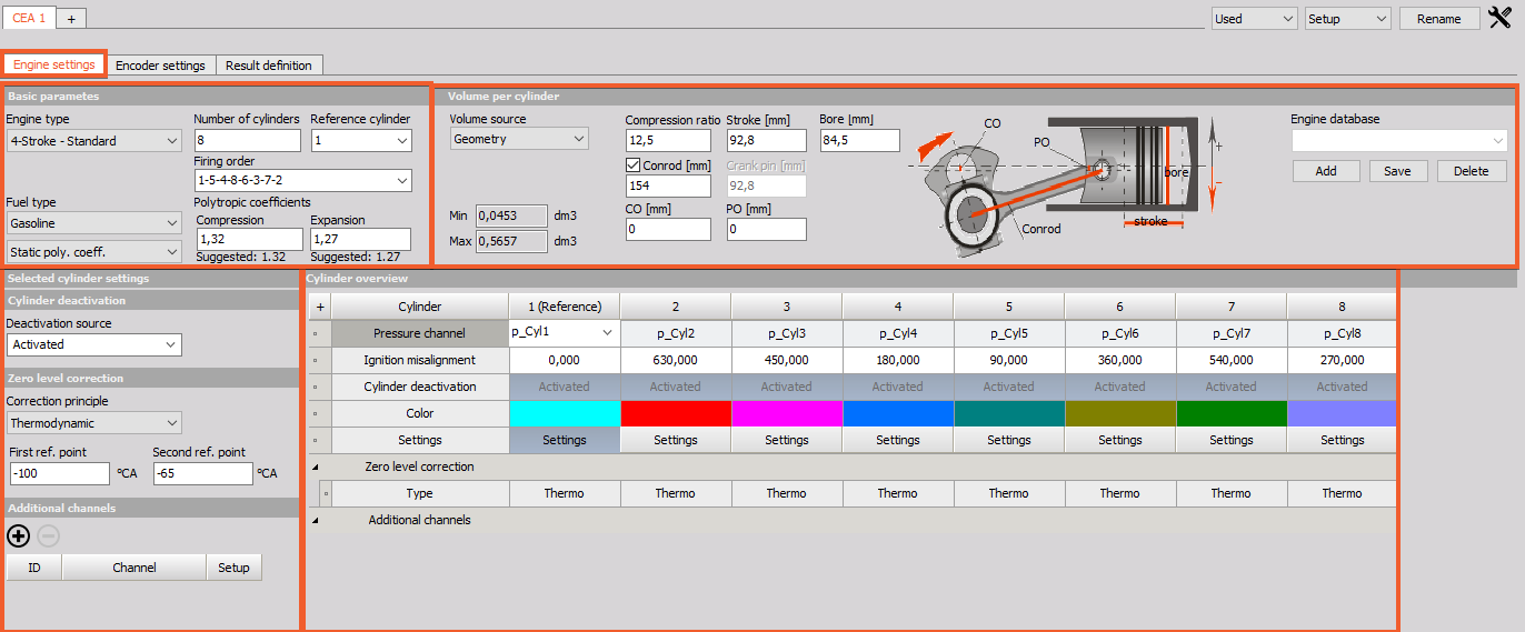
Settings and entered values for Engine CEA type are divided into the following sections:
- Engine Type
- Cylinder count
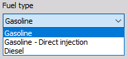
- Fuel type
- Polytropic exponent
- Volume Source
- Geometry:
- Compression, Stroke, Bore, Rod, CO, PO
- Text file
- Engine template
- Geometry:
- Min and Max volume per cylinder
- Engine templates
- Zero level correction
- Add and define additional channels
- Pressure channels definition
- Ignition misalignment
- SO1/EO1 channel & trigger levels
- Number of injections
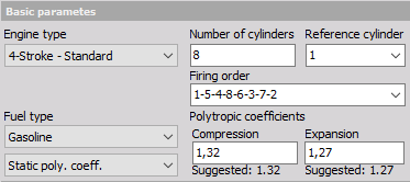
Basic parameters
Drop-down list options:
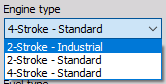
- Engine type - Engine type can be 4-stroke (for example car) or 2-stroke (motorbike).
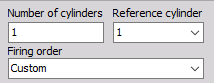
- Cylinder selection - Type in the number of cylinders, choose the reference one and select proper Firing order.
- Fuel type - Fuel type defines calculation procedures, so it is important to select the correct setting.
- Compression is the ratio between total and compressed volume:
$$ R_c = \frac{V_d + V_c}{V_c} $$
$V_d$ = swept volume
$V_c$ = clearance volume
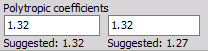
- Polytropic coefficient - The polytropic exponent is a fixed value for entire stroke. It is important for calculation of thermodynamic zero and for heat release. If you don’t know the polytropic exponent for your engine, take the suggested value for each engine and fuel type.
- Two polytropic exponent numbers are possible for input. It is possible to define completely custom numbers for the polytropic exponent where:
- the first is used for the compression stroke, where the temperature inside the cylinder is lower,
- the second number is used for the combustion (expansion) stroke where the burning process is taking place.
- Two polytropic exponent numbers are possible for input. It is possible to define completely custom numbers for the polytropic exponent where:
Volume per Cylinder
Volume Source:
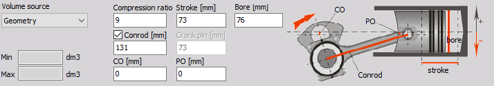
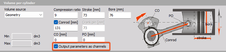
- Geometry - On the drawing on the right, you can see what values should be entered in corresponding fields.
* Compression ratio - Cylinder compression ratio
* Stroke [mm] - Stroke of the piston
* Bore [mm] - Bore of the cylinder
* Conrod [mm] - Rod length from the center of crankshaft to the center of piston pin
* Crank pin [mm] - Diameter of the crankpin
* Piston offset - PO [mm] - This is offset of the piston pin (usually zero).
* Crankshaft offset - CO [mm] - This is the offset of the crankshaft pin (usually zero).
- Text file - Single or multiple volume curves defined in a text file. It is possible to define a variable compression ratio using predefined compression curves from a text file.
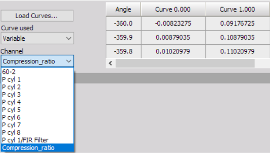
- Format for the text file is space delimited values. First row is angle, all other rows are first value curve ID, all other values are volume in dm3.

- Format for the text file is space delimited values. First row is angle, all other rows are first value curve ID, all other values are volume in dm3.
- Engine template - Volume can also be defined by custom formula in the xml file for the engine template. Refer to the engine template chapter for definition.
- Text file - Single or multiple volume curves defined in a text file. It is possible to define a variable compression ratio using predefined compression curves from a text file.
Calculated Min and Max Volume
As soon as you enter the previous values and define the cylinder pressure channel, minimum and maximum volume of the engine will be calculated and shown here.
Output parameters as channels - If the Engine type is selected as 2-Stroke - Standard or 4-Stroke - Standard, the cylinder’s Geometry parameters can be defined as individual channels.
Dynamic Shims - If the Engine type is selected as 2-Stroke - Industrial, an option to define the Shim factor with a dynamic channel.
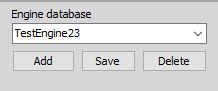
Engine database
All that information about engine type and geometry is stored in Dewesoft setup file. But you can save it to XML file (in Dewesoft directory CAEngines.xml) for easier handling of the geometry data.
Template will save the Basic parameters, Volume per Cylinder settings, Ignition misalignment and SOI, EOI trigger levels defined in Cylinder overview into engine database.
Buttons:
- Add - adds new template - after Adding new template the name should be entered
- Delete - deletes currently selected template
- Save - saves changes to currently selected template
Cylinder Overview and Selected Cylinder settings
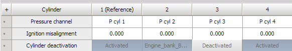
Cylinder overview
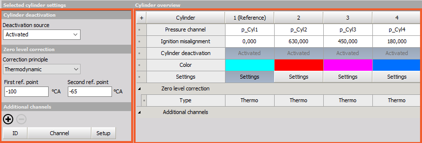
- Cylinder - Reference cylinder is the one that is used for all calculations as base (it is the one which has zero misalignment). Select it by clicking in the cylinder row. In our example that is cylinder 1 (grayed).
- Pressure channel - In this row you select pressure channel for a given cylinder. At least reference cylinder needs pressure channel for correct calculations. Channels must be set correctly in the Analog setup (scaling, name, color).
- Ignition misalig. [°CA] - This is how cylinders are fired, with what delay (in degrees). You must know this for your engine.
- Additional channels - Additional channels are not used in any calculations but can be shown in displays.
Selected Cylinder settings
- Cylinder deactivation has two purposes - to ignore deactivated cylinder results for average value calculations (MEP, work, power, torque, thermodynamics) if a cylinder is actually not firing. It can also be used if one of the pressures sensors is faulty.
- You have 3 levels of Cylinder deactivation:
- Activated: cylinder permanently activated
- Deactivated: Cylinder permanently deactivated
- From channel: Channel can be used to activate or deactivate a cylinder. If channel value is lower or equal than threshold value, the cylinder is deactivated.
- If a cylinder is deactivated, there is going to be an additional average output available for all deactivated cylinders combined.
- You have 3 levels of Cylinder deactivation:
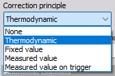
Zero level correction - Thermodynamic zero, fixed value, measured value, none, measured value on trigger.
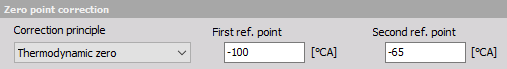
Correction principle - There are four basic correction principles for the zero point correction. Thermodynamic zero assumes polytropic compression and finds the absolute pressure offset according to it. The polytropic exponent, the start and end angle for this calculation needs to fit the real compression (without ignition).
 Channels must be set correctly in the Analog setup (scaling, name, color).
- Additional channels - Additional channels can be applied to each cylinder. These channels are aligned with the corresponding cylinder and will be available in the CEA-Scope diagram. As an example you can also apply the fuel pressure signal or current probe in order to display it together with the pressure signal. By clicking on the settings button for each cylinder separately, additional channels can be added on the left side by clicking on the ‘+’ button. All signals that are added as additional channels will be recalculated into the angle domain and available on the CEA scope to be compared together with cylinder pressure. Additional channels are also shifted for the ignition misalignment angle that is specified for the cylinder which has the corresponding additional channel.
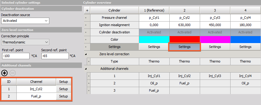 In this example below an injection signal is applied. The number of injections (events) is set to 3, and the start trigger level is set to 2V, where end trigger level is set to 1V. Each time the injection signal crosses 2V it will return the angle position, related to the cylinder where it is applied [deg]. Number of injections needs to be set to generate the output channels in advance. The result will be the start angle and the stop angle [deg] of the applied signal.
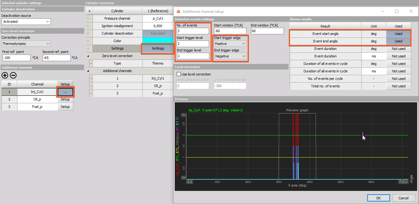 Number of injections (events) needs to be set to generate the output channels in advance. If there is only one injection and max. No injections is set as 5, only the first SOI and first EOI will show an angle that is detected, all other results will be 0. Similar is also the other way around, if there are 5 injections and there is only 1 injection set as the maximum number, only the first will be detected and all others will be ignored.
The same is true for EOI: if the signal crosses 1V (neg. edge) the position will be returned[deg].
The unit of the trigger levels are related to the channel scaling on the analogue input. In this case Ignition is scaled in voltage [V].
Number of injections (events) needs to be set to generate the output channels in advance. If there is only one injection and max. No injections is set as 5, only the first SOI and first EOI will show an angle that is detected, all other results will be 0. Similar is also the other way around, if there are 5 injections and there is only 1 injection set as the maximum number, only the first will be detected and all others will be ignored.
The same is true for EOI: if the signal crosses 1V (neg. edge) the position will be returned[deg].
The unit of the trigger levels are related to the channel scaling on the analogue input. In this case Ignition is scaled in voltage [V].