Encoder Settings
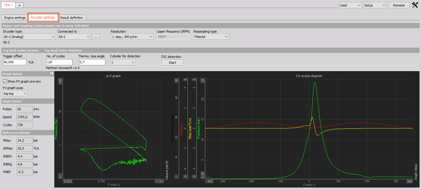
Go to the Encoder settings tab in CEA in order to setup the Angle sensor for Combustion analysis:
Settings and entered values for Encoder type are divided on sections:
-
- Angle sensor type
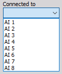
- Connected to
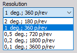
- Resolution
- Upper frequency [RPM]
- Resampling type
-
- Trigger offset
- Number of cycles
- Thermo loss angle
- Cylinder for detection
- Graph details
- Angle sensor and Reference cylinder Values
- Top dead center in Measure mode
Sensor and sampling
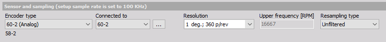
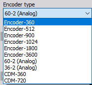
Drop-down list options:
- Encoder type - Angle sensor depends on what sensor we connected. Select the proper encoder type. If you cannot find the used sensor, create a new one under Options -> Editor -> Counter sensors.
In order to enter Angle sensor Math setting (filtering,…) click on the three-dot icon beside the Connected to drop-down menu:

Connected to - Here we define the physical connection of the sensor. If use an external clock with CA-CPU, it will show the CA-CPU inputs. If we use the internal clock, it will offer the counter inputs for encoder and CDM sensors and analog inputs for Geartooth with double or missing teeth.
Resolution - The resolution will define the number of points per one engine revolution. A higher number will give higher accuracy, but will also bring more calculation load.
Resampling Type - here you can choose an unfiltered method which is linear interpolation from the time to the angle domain. The filtered type is based on a FIR polyphase decimator with a filter frequency of angle resolution * 2 to avoid aliasing effects in the angle domain data.
For information about Angle sensor setup see -> General mathematics modules -> Angle sensor math.
Top dead center detection
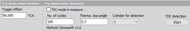
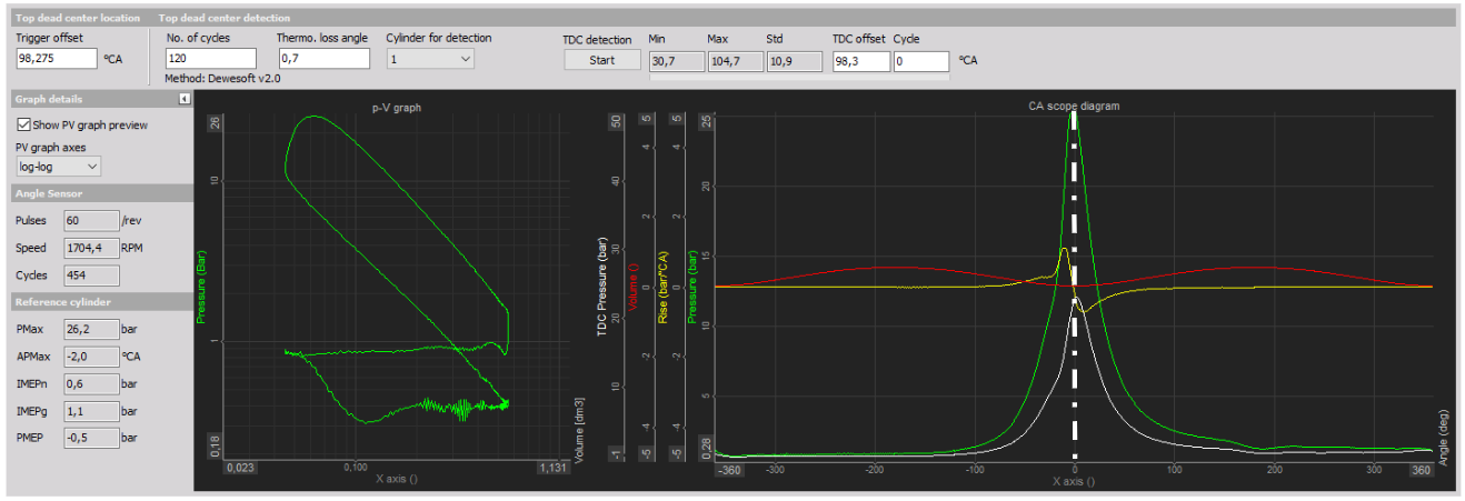
Trigger offset is the offset from the trigger to top dead center of the reference cylinder.
Top dead center detection is used to shift the reference cylinder pressure to 0 deg. The offset between angle sensor zero and the TDC position of the reference cylinder is called the trigger offset. This can be entered manually, or it can be measured.
- No. of cycles - The number of cycles defines the number of averages to take in the TDC detection procedure.
- Thermo. loss angle - TDC detection procedure will search for pressure peak, but this peak is delayed for some angle compared to the top dead center. We enter this offset in this field.
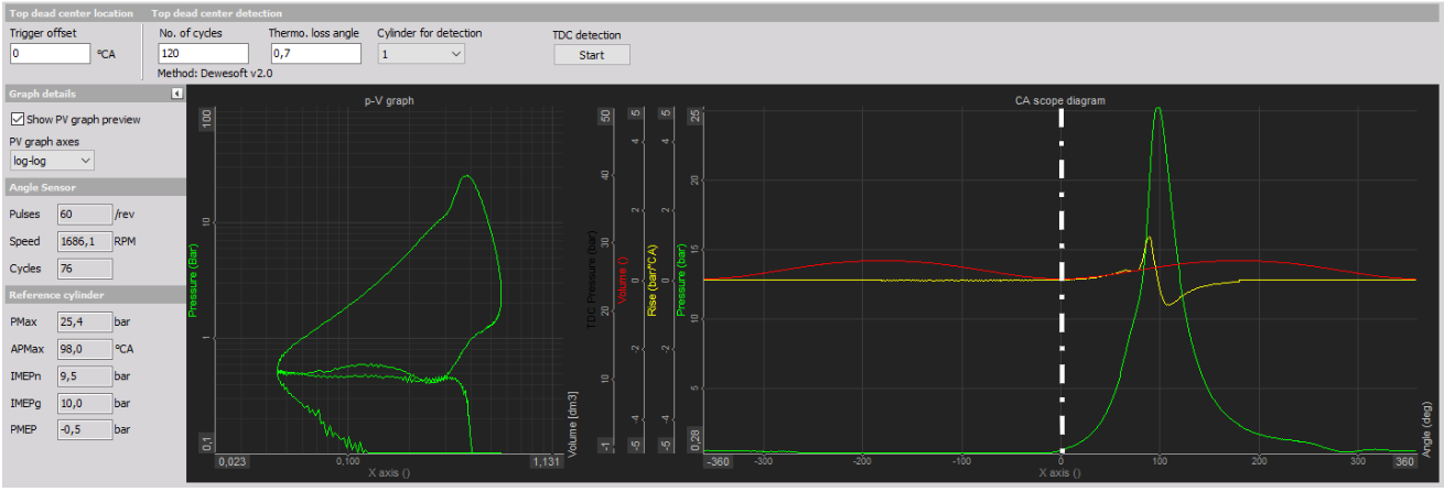
When the Start button is selected, a table with values appear instead on the right side table:

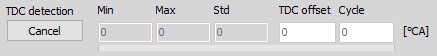
Now the Start button changes to Cancel button and by selecting this we can stop TDC detection (button change again to Start).

After TDC detection is finished, the average value (which includes the Thermodynamic Loss angle) will be set automatically for the trigger offset.
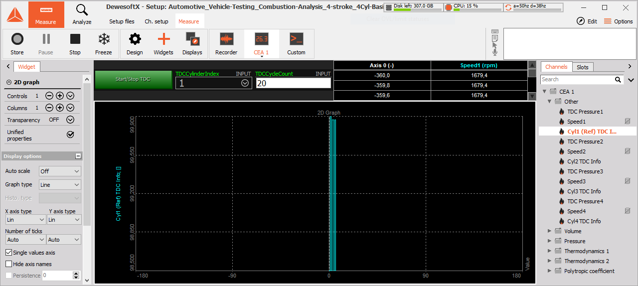
Top dead center in Measure mode
We can chose to make TDC alignment in the Measure mode within DewesoftX. CEA has preset the TDC display on which we must assign three control channels to define the start/stop, TDC Cyl Index and TDC Cycle count.
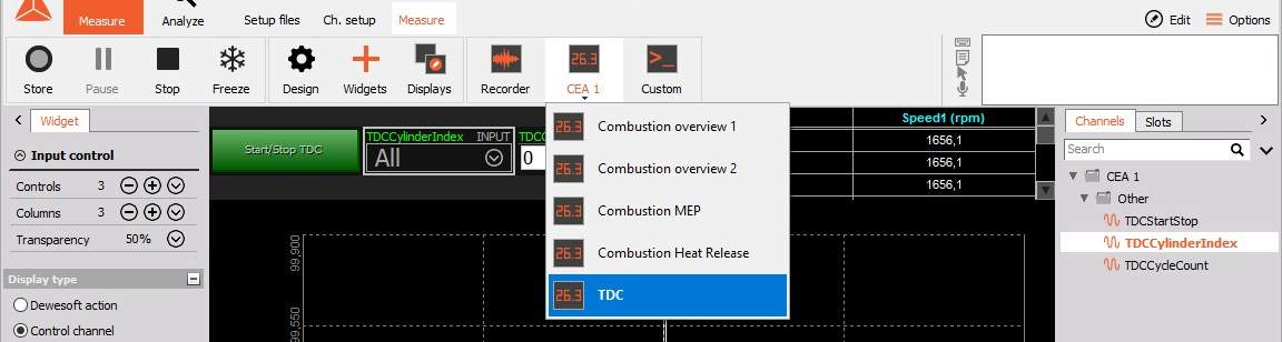
When we press start the TDC alignment will be made after achieved CyclesCount.