Angle sensor math
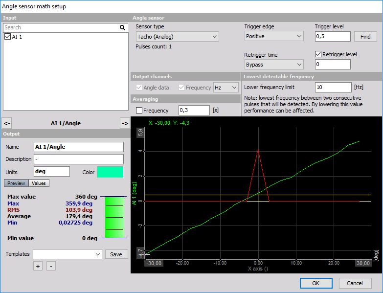
When you press the Setup button on new activated Angle sensor line, the following Angle sensor setup window will open:
For detailed information about basic settings of the input and output channels see -> Setup screen and basic operation.
The input for the angle sensor math can be any analog trigger signal (like tacho - 1 time per revolution or automotive 60-2 sensor). In both cases, we need some mathematics to calculate the current angle and the frequency of the incoming signal. In both cases, the signal needs to be connected to the analog input of the instrument. Then we need to select this signal, select the Sensor type from the list of the available sensor or by defining a new sensor type in the counter sensor form. Next, we can simply press Find function to determine the trigger levels. In most cases, this function works already, but in some cases, we need to define the trigger levels manually by settings the Trigger level and Re-trigger level input field. Next, we can define the Re-trigger time. This is a hold off in which the signal is not checked for triggers. This is useful to prevent trigger glitches. The graph below will show the signal levels for easier determination if the trigger is working fine.
The output from this math module is the:
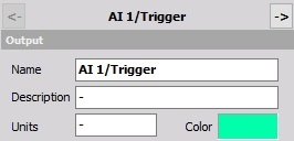
- Angle: Angle channel as we can see from the picture above and Trigger channel
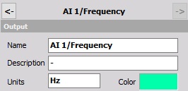
- Frequency: Frequency channel
These channels can be selected by checking the appropriated box in the Output channels section.
This angle can be used in basically all advanced Dewesoft modules like CA, order tracking and torsional vibration or standalone just to get the signal frequency.
The nice feature of this module is that it implements calculation delay. For sensor like 60-2 it is not possible to determine the angle until the first gap is recognized. For that time the angle sensor math holds all the calculations and with the first gap also calculates the data for the first turn before the gap. This is crucial for some applications like the cold start of the engine.
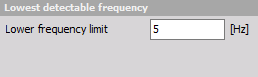
We can change the lowest detectable frequency by editing the Lower frequency limit edit field. Using this edit field we can specify the lowest rotation frequency angle sensor math is able to detect. By lowering this value, performance can be affected. The minimum allowed input depends on acquisition sample rate and “Sync DB buffer length” found inside Settings > Performance > Memory.
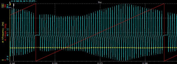
Please be aware that the quality and the resolution of the data depend on the analog sample rate. If the sample rate is low, the output (especially the signal frequency) will not be exact. So it is recommended to use higher sampling rates (like 50 kHz) for these calculations. The results can be improved with the usage of Averaging on Frequency, which is defined in the setup screen. This will average the frequency results in the time period which we define.