Counters
The Dewesoft Counter module is used to perform rotational speed and angle measurements, trigger detection, counting and more. The counter setup depends on the used hardware platform.
Typical applications are:
- Event counting (gated event and up/down counting)
- Waveform timing (period, pulse-width, duty cycle, two edge separation)
- Sensor mode (encoder, tacho, geartooth, …)
This Counter page and related sub-pages contains information about DAQ hardware related counter settings.
For information about the software math used to process Counter channels please go to the page Counter Math module.
For information about counter sensor types and how to configure them please go to the page Counter Sensors.
General / Sensors parameters
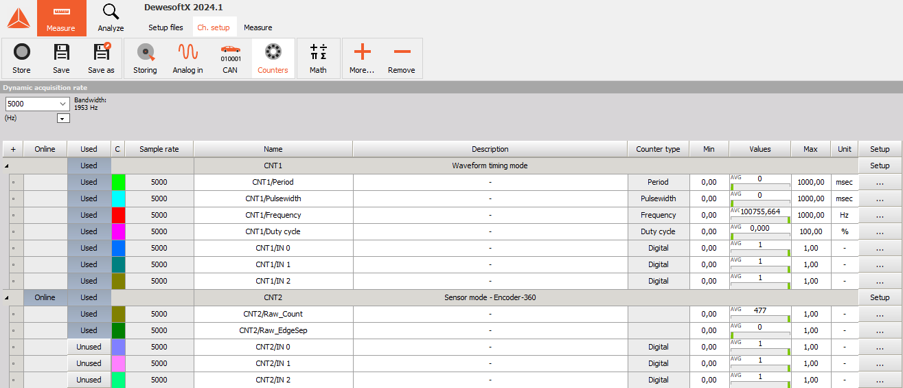
When you select a Counter tab on Dewesoft Setup screen, the Counter module will appear on the lower part of the screen:
For instructions on how to Add new module see -> Setup -> Add module.
For information about Slot, On/Off, C and Name column see - Channel grid.
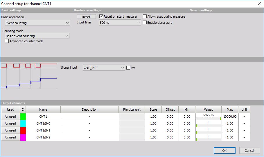
Press Setup in SETUP column to do the base counter settings in Channel setup window:
- General parameters - are similar to the analog input channel settings and contain the Channel name, Units, Color and Min and
Max value -> see -> General channel settings.
- Sensors parameters - are similar to the analog input settings and contain the Sensor groups, Sensors and Description: -> see -> Sensor settings.
Hardware parameters
Set and number of parameters (settings fields) are dependent on the used hardware.
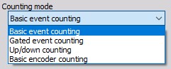
Option of this field depends on the used hardware and applications respectively and can be:
- Event, gated and up/down counting
- Encoder measurements -> Advanced counter mode
- Period and pulsewidth measurements -> Timing modes
- two pulse edge separation
For information about Hardware parameters setup click on caption above.
Some common counter Hardware parameter expansions are:
- Reset on start measure
Check this box to counter reset on start of measurement.
- Reset button
With a click on the button we can reset the actual counter to zero.

- Lowest detectable frequency
Using this edit field we can specify the lowest rotation frequency our counter sensor is able to detect. By lowering this value, performance can be affected. The minimum allowed input depends on acquisition sample rate, “Sync DB buffer length” found inside Settings > Performance > Memory, and “Maximum calculation delay” found inside Settings > Advanced > Performance.
Below the edit field we also get an overview of a hint about the maximum rotation frequency counter sensor is able to detect. This frequency depends on the type of sensor, and the acquisition sampling rate.
NOTE: These are hard limits, meaning that if the rotation falls below the exactly specified lower frequency limit or exceeds the approximate highest limit, it is no longer guaranteed that counters will correctly calculate the outputs.

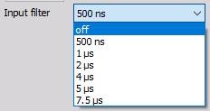
- Input filter
The filter is an important setting to prevent double counts. We need to choose the filter to react a bit faster than what we expect our events to be or, with a different logic; we need to set them a bit slower than what we expect to have glitches in the signal.
Except for frequency counter that can be selected in this field from the drop-down list value of input filter in ns or off for no filter. An option of this field depends on the used hardware (base clock).
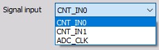
- Signal input
Also, the Signal input depends on the used hardware, for example Source Pin (external clock), 100 kHz or 20 MHz (internal clocks) can be selected from the drop-down list in this field.
- Signal inverting
When the normal state is high, sometimes it is nice to invert the signal by choosing the inv checkbox beside the signal field. This function serves to invert the input signal (the normal state is than low), which can be particularly useful in scenarios where the sensor connection may be faulty. Additionally, this feature is handy when desiring counting on the falling edge of the original (non-inverted) signal. By choosing to invert the input signal and subsequently counting the rising edges of the inverted signal, the same results are achieved as counting the falling edges of the non-inverted signal.

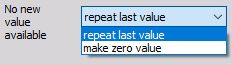
- No new value available
The field no new value available tells the software what to do when no new value is available. The new value is calculated only when a signal changes the value from low to high. Therefore the value can’t be calculated most of the time.
If we choose to repeat the last value, then the same value will be added until a new transition is made. Alternately, we can select make zero value when no new value is available, so we will have only spikes at the points of new data and the rest of the data the value will be zero.
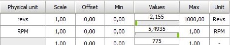
- Scaling - the scaling area can be used to adapt the sensor to your system by entering the desired value of:
- counts for Events and Encoder Counter mode
- ms (milliseconds) for Period Counter mode
- Hz for Frequency Counter mode
in upper field and value for ‘equals’ in channel Units (entered in General part of this setup window) in lower fields or by pressing Calibrate from the current button.
for example, the connected sensor delivers 1800 pulses per 360 degrees
On right part Scaling section of Channel setup for channel CNTn window:
- Current unscaled value [cntUnit=counts, ms or Hz]
- Current scaled value [Units= -, m, Hz….]
and on the lower part, the actual equation for Output value is displayed.