Analog In
In the DewesoftX Analog in module, you can set all analog input channel which will be used during measurement. This module will be added by default to every setup file. The menu consists of three parts:
- Dynamic acquisition rate - defines the sample rate of analog, counter and digital channel
- Channel actions - shortcuts to amplifier commands
- Channel list - Information and settings in columns including the Channel setup button.
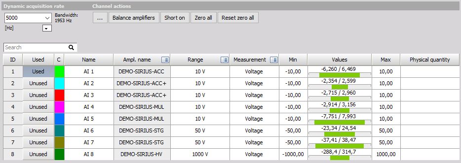
Dynamic Acquisition Rate
Enter or select a sample rate to be used for dynamic acquisition. The maximum allowed sample rate will vary according to which A/D board you have installed, and how many channels are activated for recording.
When storing dynamically, every sample point is recorded in the file. For example, if you have ten channels activated, and the dynamic acquisition rate is 5000 samples/sec/ch, the resulting data file will contain 5000 samples per second of acquisition for each channel.
NOTE: Please refer to the Storing module manual for more information on dynamic and reduced acquisition rates.
Only synchronous channels are directly influenced by the dynamic acquisition rate, i.e. increasing the sample rate will increase the amount of data points. Asynchronous channels’ (CAN, GPS, …) data points are not directly influenced by the sample rate, but the dynamic rate has to be faster than the rate of data coming from the asynchronous device.
NOTE: Set the sampling rate before you do anything else; this setting will also be used for the setup. This is important to achieve a useful scaling!
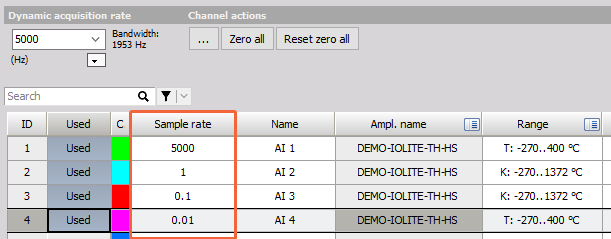
Adjust sampling rate below 10Hz
If you want to store data with a sampling rate lower than 10Hz, you will need to adjust it in the Sampling Rate column in the channels list. An additional filter for anti aliasing will be activated. These channels will be stored as asynchronous channels in the data file.
Bandwidth Mode
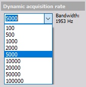
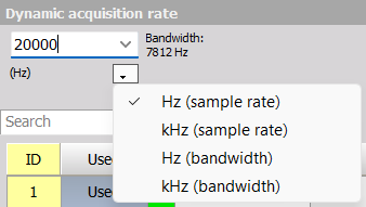
If your application requires focusing on the bandwidth of the signal, you can switch the Acquisition rate setting from Sample rate to Bandwidth. Click on the dropdown menu icon to get the four different options as shown below.
For example, if you measure vibrations with known frequency characteristics, it’s more convenient to set the measuremet up with regard to the bandwidth of the signal. If the vibration signal has a maximum frequency of no more than 100 kHz, you can set the bandwidth to 100 kHz to achieve optimal measuring settings.
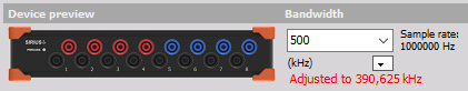
When setting the desired bandwidth, the sample rate is adjusted according to it. If you exceed the bandwidth limitation, a red warning will appear and bandwidth will be adjusted.
$$ Maximum \ bandwidth = \frac{Sample \ rate}{2.56} $$
In the example below, SIRIUS has a maximum sample rate of 1 MHz so the bandwidth can’t exceed 390,625 kHz
NOTE: This bandwidth setting is not hardware related and is simply a helpful way to choose the optimal sampling rate. For the bandwidth (passband, aliasing-free bandwidth) of a specific device please refer to the technical reference manual of the device.
Channel Actions
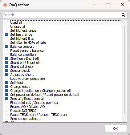
You can choose which channel actions will be shown in the module menu by clicking the … button.

A list of actions applicable to the channels in your current setup will appear.
- Used all - Set all channels to Used.
- Unused all - Set all channels to Unused.
- Set highest range - Set ranges of all amplifiers to the highest possible input range.
- Set best range - Use real-time data and set the range of all amplifiers to the best possible fit.
- Set highest filter - Set the analog input filters of all amplifiers to the highest possible values or switch it to off, if possible.
- Set filter to 40% of rate - will set the analog input filter of all amplifiers to the nearest value of the Nyquist frequency (40% of sample rate) to prevent aliasing.
- Balance sensors - Balances all bridge sensors.
- Reset sensors balance - Resets the sensor balance of all bridge sensors.
- Balance amplifiers - Balances all amplifiers, zeroing their offset.
- Short on / Short off - Shorts pins 2 and 7 of the amplifiers, showing their offset.
- Shunt on / Shunt off - Shunts a known resistor to one of the resistors of the bridge amplifiers. This creates an unbalance needed for the Shunt cal check.
- Shunt cal check - Calculates the error of the shunt calibration using the Shunt calibration target for all bridge amplifiers.
- Sensor check - Same as Shunt cal check.
- Adjust by shunt - Used for manual calibration.
- Leadwire compensation - Cancels out the wire resistance for sensors in “quarter bridge 3 wire mode”.
- Self-test - Performs a self-test for bridge amplifiers.
- Charge reset - Resets the charge modules.
- Charge injection on / Charge injection off - Outputs a sine 1V 20Hz signal to measure capacitance.
- Set power on default / Reset power on default - Sets or resets current channel settings as default on device start-up.
- Zero all / Reset zero all - Zeroes all channels.
- First point cal. / Second point cal. - Sets the first or second calibration point based on the current short average measurement of signals for all sensors.
- Enable AO / Disable AO - Enables or disables signal conditioning.
- Rescan DSI/TEDS - Rescans the TEDS chip of the sensors.
- Pause TEDS scan / Resume TEDS scan - Pauses or resumes the TEDS scan.
- Zero sensor calibrate - Sets the sensor calibration date of all sensors to the current date.
- Alignment - Used to align MEMS sensor axes.
Channel List
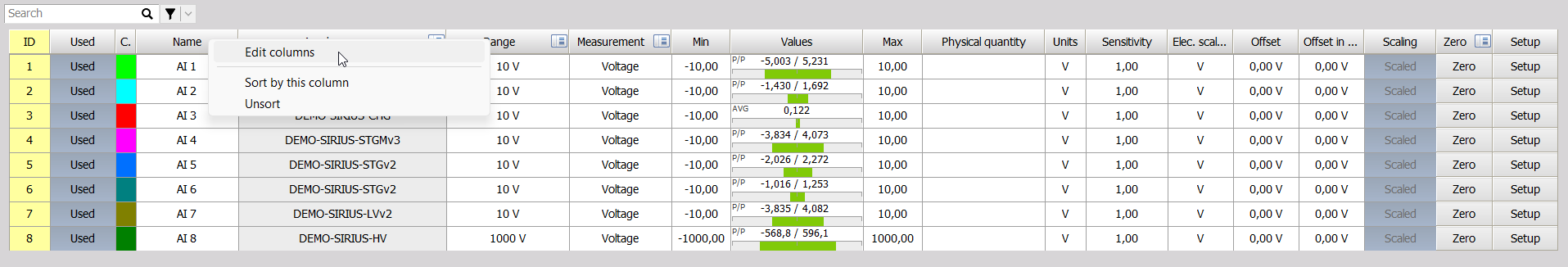
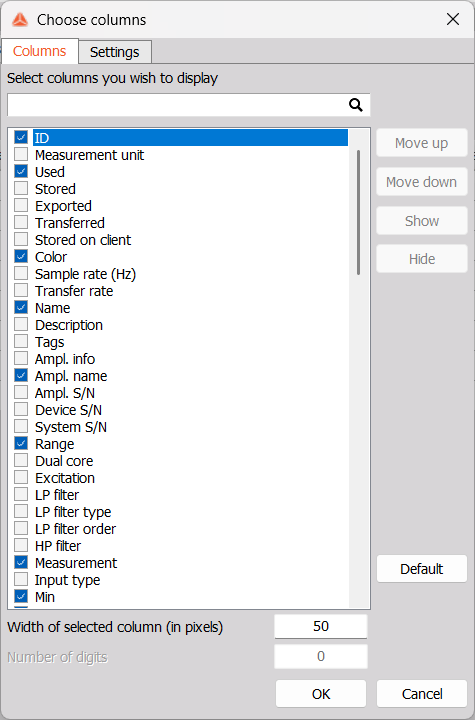
All analog inputs will be listed in the channels list. You can customize the information displayed by right clicking any column name and selecting Edit columns:
The Choose columns menu will appear:
Channel Setup
NOTE: For interactive training, please visit Dewesoft Online Training - Basic Measurement with Dewesoft DAQ Hardware.
To set a channel up, press the Setup button in the last column of its row. The Setup window will appear:
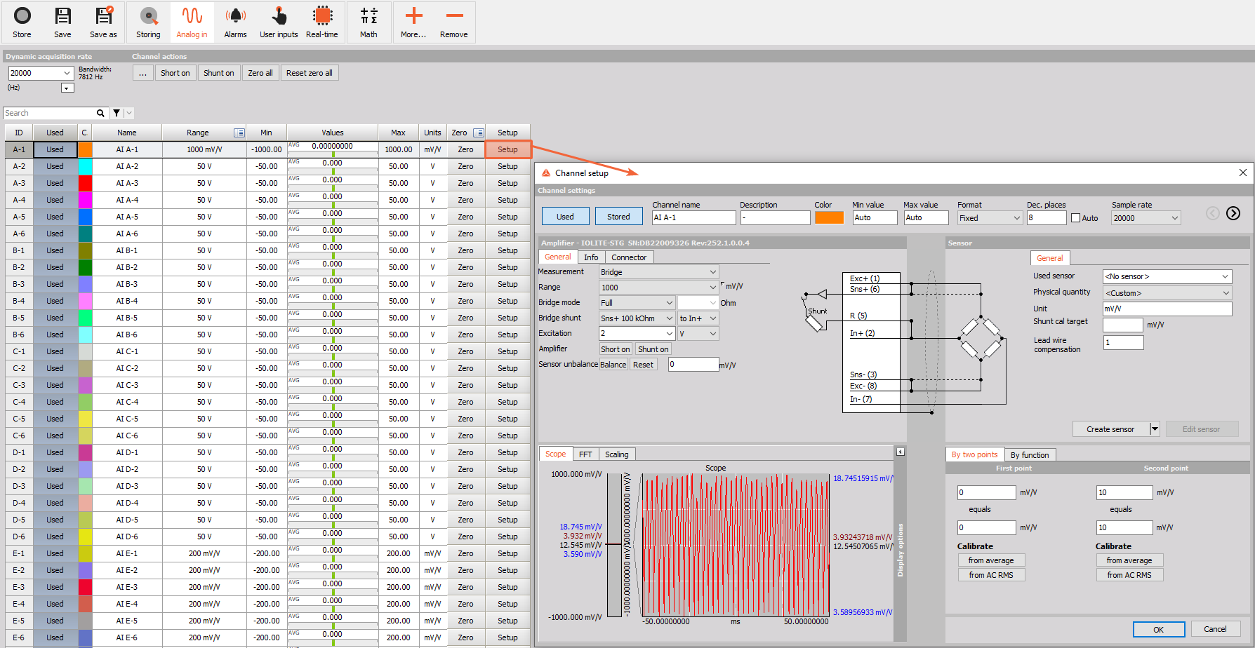
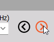
You can switch between channels without closing this window by using the arrows in the upper right corner.
The channel setup window is divided into segments:
- Channel settings - General settings, such as Channel name, Description, Color, display range - Min value, Max value, format, and Sample rate divider.
- Amplifier settings - define and set amplifier settings: Non-programmable, series and special programmable modules.
- Sensor settings - Define and set sensors information and data in the sensor database
- Live data preview - Real time display of the acquired signal.
- Scaling - Perform scaling and manual or automated calibration; set a dynamic representation of your signal.
- Calibrate - Quickly calibrate directly to DC and AC signal sources.
Confirm all changes by selecting OK bottom or discard changes with Cancel button and return to Analog input channel Setup screen.
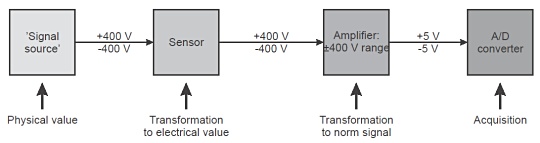
Example:
A voltage up to ±400 V (=signal source) will be measured with cables (=’sensor’) connected to a high voltage module (=amplifier).