Resolver sensor
Resolver sensors are used for measuring rotational speeds and angle positions. The Resolver sensor math module is used to decode such signals from resolver sensors.
An example of where resolver sensors are commonly used is for Motor analysis.
A resolver sensor transforms energy in wire windings into a sine and a cosine signal which will have a frequency relating to the rotational shaft speed. The resolver sensor math module uses filters and math internally to decode the sine and cosine signal magnitude values into angle positions and derived speeds.
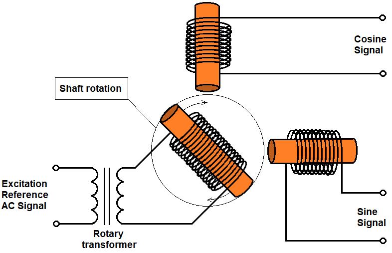
Resolver sensors come in multiple variants. For example, a rotor excited transmitter resolver has three windings: an excitation reference winding, a sine winding, and a cosine winding. Here, the excitation reference winding is used to drive a high frequency AC signal on the resolver rotor part. The sine and cosine windings on the stator part are used to detect the induced excitation signal, but now modulated by the mechanical rotation speed.
A sketch of such a resolver type is shown below:
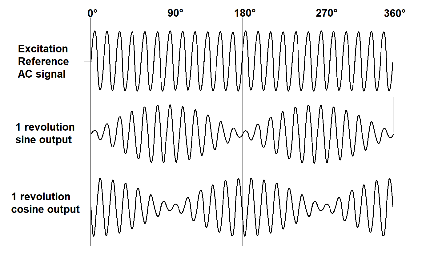
The excitation signal together with the output modulated sine and cosine signals are sketched below to illustrate the modulation and the phase shift between the sine and cosine outputs.
Adding Resolver sensor math module to a setup
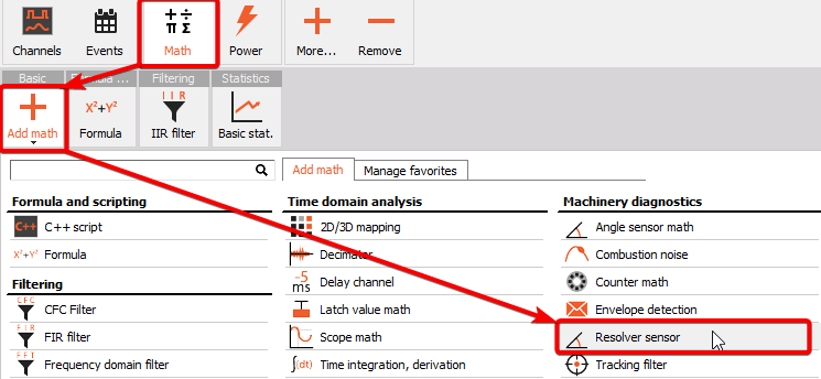
The Resolver sensor math module can be added to the setup under Math by pressing the Add math button and then selecting the Resolver sensor module, located under the Machinery diagnostics section:
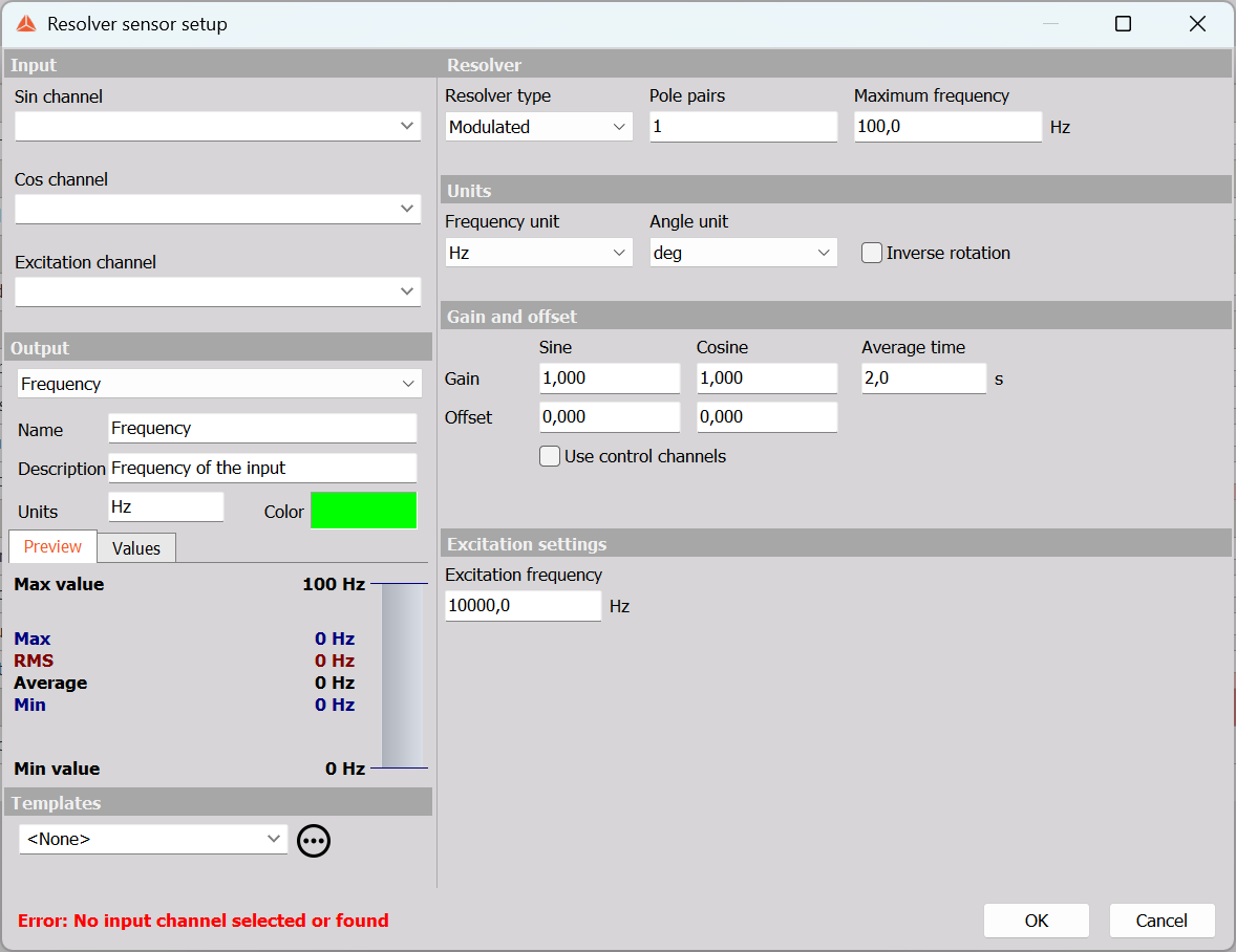
When you add the math module or press the Setup button on newly activated Resolver sensor module, the following Resolver sensor setup window will open:
Linked to Motor Power Analysis
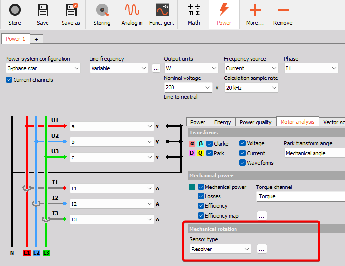
The Resolver sensor module can also directly be configured in the Power module under the Motor analysis tab. For Motor Power analysis the resolver module can be used as the speed source for the efficiency mapping output:
Input section
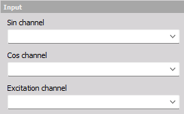
The Input section is used to select the Sin and Cos channels from the resolver sensor, and also the Excitation channel if the Resolver Type is set to Modulated.
NOTE: The Dynamic acquisition rate should be higher or equal to 3 times the excitation frequency.
Output section
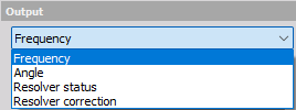
The Output section shows all the produced output channels:
- Frequency - the rotation speed expressed in revolutions per second [Hz], or revolutions per minute [RPM].
- Display widget: Recorder or Digital meter.
- Angle - the rotation angle expressed in degrees [deg], or radians [rad].
- Display widget: Recorder or Digital meter.
- Resolver status - the state of the resolver correction process.
- Display widget: Discrete display.
- Resolver correction - a control channel for managing when to start the Correction determination process.
- Display widget: Input control.
Resolver setup section
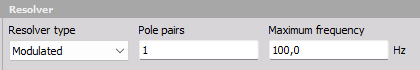
The Resolver section under the module setup is used to select the:
- Resolver type
- Pole pairs
- Maximum frequency
Resolver type
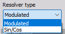
The Resolver sensor module supports resolver sensors with and without AC voltage excitation:
- Modulated: used for Transmitter resolver types that are driven by an excitation AC voltage.
- Sin/Cos: used for Transformer resolver types without excitation AC voltage
Pole pairs
Pole pairs are used to specify the number of resolver pole pairs on the rotor part. Two-pole-resolver types have 1 pole pair, whereas Multi-pole-resolver types can have more.
Maximum frequency
The maximum frequency is used for low-pass filtering of the sine and cosine signals. A low-pass filter can improve the angle and speed determination by reducing noise on the input signals, The low-pass filter will have a flat frequency response up to the Maximum frequency, and the sample rate will be kept having a value factors higher than the Max frequency setting.
Output units section
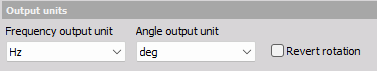
The Output units section determines how the rotation outputs should be scaled
Frequency output unit
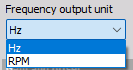
The rotation speed can be set to either:
- [Hz] - rate of rotation per second - the rotation Frequency.
- [RPM] - rate of rotation per minute - Rounds Per Minute.
Angle output unit
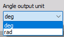
The rotation angle can be set to either:
- [deg] - rotational displacement expressed in degrees.
- [rad] - rotational displacement expressed in radians.
Revert
Enabling Revert will change the Sin and Cos input channels around, and in practice this will invert the angle and speed channel values from positive to negative or opposite.
Gain and offset section
The Gain and offset section is used to increase accuracy and reduce the effects of initial settling of the processing of the resolver sensor module.
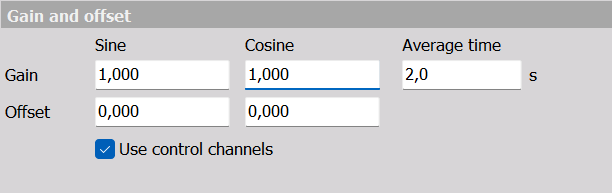
The Gain and Offset values for the Sin and Cos channels can be typed in manually or determined automatically.
Manual Gain and Offset
If the Sin and Cos channels have known Gain and Offset levels then they can be typed in manually. For example, e.g. the Sin channel might have a DC offset of 0.23 V and a gain level of 2.43 V.
When the Resolver type is set to Modulated the Gain and Offset values can be more complex and difficult to determine manually, and here using automatic value determination can be convenient.
Automatic Gain and Offset
The automatic Gain and Offset determination can be performed over a user-defined Average time duration, both while in Measure mode and in Review mode.
Correction in Measure mode
In Measure mode the Gain and Offset values can be automatically determined either by using:
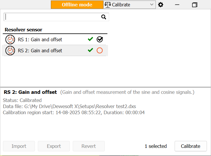
- Live calibration - found in the Measure screen through the Calibrate button in the top right cornor:

When opening the Calibrate menu you can calibrate/correct the resolver gain and offset as shown below:
- Resolver control channels - using the enabled Resolver control channels in the Measure screen.
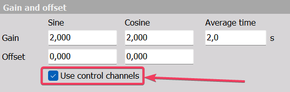
By enabling the checkbox for Use control channels, additional channels will be available under Measure which can be used to set up and control when to start the Gain and Offset determination.
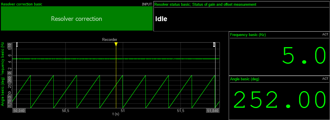
By adding Input control widget buttons resolver Correction can be managed as illustrated below:
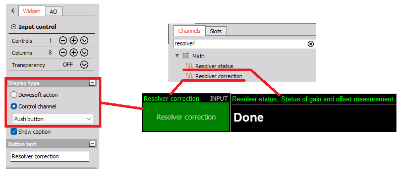
The Resolver status channel can be added to a Discrete display widget to show the status of the Correction process.
The Resolver correction channel can be added to an Input control display widget set as a Push button type, to push when to start the Correction process.
NOTE:
1. The rotation speed should be kept steady in the time interval used for gain and offset correction.
2. The minimum rotation speed for performing Gain and Offset correction measurements are 10 Hz, 600 rpm. If the speed is too low it will be indicated on the Resolver status channel as shown below:

Correction in Analyze mode
In Analyze mode Gain and Offset correction can be applied to already stored data.
The Gain and Offset values can be determined automatically based on a selected time region.
The time region to use is selected either by zooming in on a Recorder widget or the header widget, as shown below:

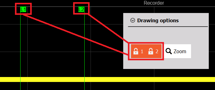
Or the region can be selected by locking the L1 and L2 cursors on a Recorder widget, as below:
After selecting a time region, where the rotation speed is being steady, click on the Calibrate icon in the top right of the screen, select the resolver sensor and click Calibrate.
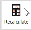
Now, after the gain and offset has been corrected, zoom out and select the full data file and press Recalculate. In this way the correction will be applied to all the data.
Use of Templates
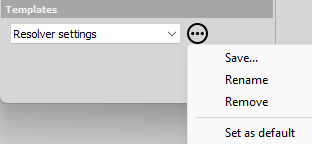
In cases where the same Gain and Offset values should be applied to multiple stored data files, a module setup Template can be saved and applied on all files to easily align the resolver setup parameter values. Template settings are shown below:
For example, if a set of measurements have been acquired with no resolver correction applied, then a Resolver setup template can be applied with settings containing valid Gain and Offset values.
Also, this is useful if some of the other measurements do not have a steady speed range where such Correction values would be possible to be determined.
Excitation settings section
The Excitation frequency is relevant for Modulated resolver sensor types. For modulated resolver types the Excitation frequency should be set equal to the excitation AC voltage frequency.
The Excitation frequency is used to determine the signal envelope of the modulated Sin and Cos signals by performing demodulation.
For Modulated Resolver types the sample rate is being kept factors above the excitation frequency in order to maintain clear information of the modulated signals.