Envelope detection
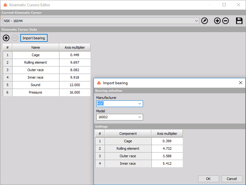
NOTE: Bearing cursors were moved to Kinematic Cursors database (Options->Editors->Kinematic Cursors).
In the Kinematic cursor editor, add a new bearing or select it from the existing database, selecting the Append bearing option.
To use the Kinematic cursor we have to add the Envelope detection math channel.
When you press the Setup button or open a new math Envelope detection line, the following setup window will open:
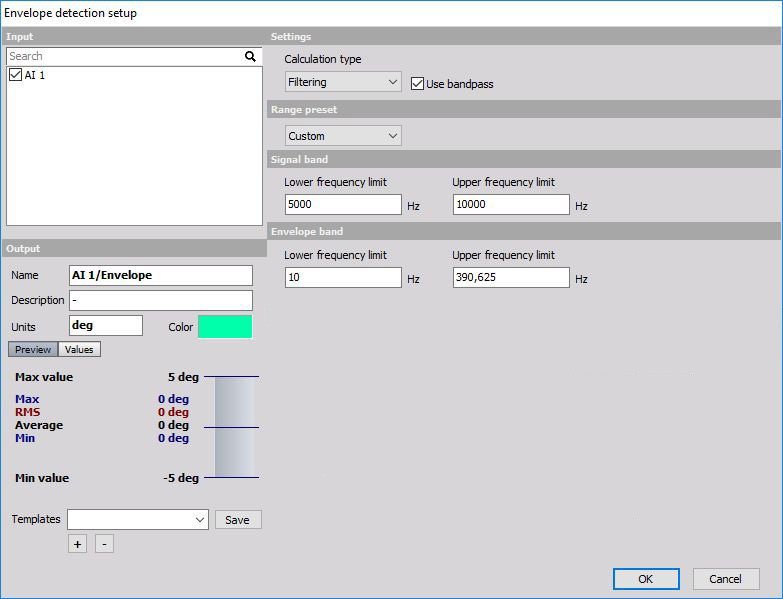
Envelope detection is a procedure for early detecting of faults on ball bearings. Envelope detector has several stages and for each stage, the parameters must be set:
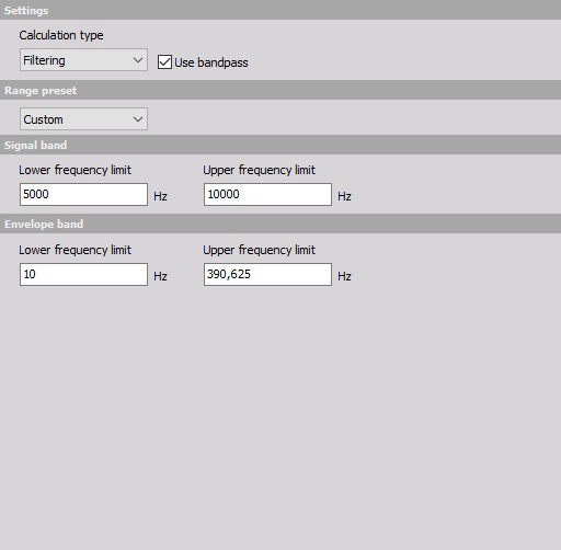
Calculation type defines the principle of calculation.
- Filtering - uses filter procedure for envelope calculation. Filtering is a standard procedure for calculating envelope used also in other implementations.
- Peak detection - uses the procedure of detecting peak values in the signal. Peak detection is a procedure which calculates amplitudes more exact than filtering.
- Bandpass - checkbox enables or disables the first stage of calculation - band pass filtering. |
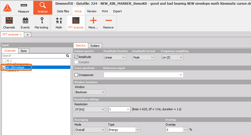
Channels from Envelope detection math must be used as an input channel into FFT analyzer.
Acceleration sensor measures the entire frequency range and acquires unbalance, misalignment and other faults on the machine. Ball bearing errors have very low energy and therefore is a small contribution in the entire frequency spectrum.
When an error of the ball bearing occurs, it will produce ringing with a frequency which corresponds to its natural frequency. This ringing will repeat each time when a damaged part of the ball hits the ring or vice versa. We also have to know that inner ring, outer ring, cage and balls have different typical repeating frequency depending on the geometry of the bearing and the rotational frequency.
To only focus on these high frequencies of the ringing, we have to look at the original frequency spectrum. We have generated a sine wave which has a small 10 kHz rings on top. In the frequency domain, we don’t see the frequency of repeating ringing, but only a major sine wave (could come from unbalancing) and very high frequency coming from the bearing.
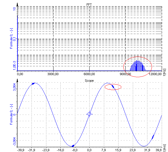
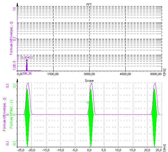
Bandpass filtering in the envelope detector must be set to remove all components except ringing of the ball bearing. This can be usually found around 10 kHz. In the example, we have set the lower frequency limit to 6 kHz and the upper limit to 12 kHz in order to get all the energy. The signal after filtering should look like in the picture below.

Only high frequency remains, but we still don’t see the main low frequency with which the rings are repeating. Therefore we have to apply envelope to the signal. Envelope will draw a curve around the peaks of the signal, producing only positive part of the data. To get a correct amplitude, we have to choose the Envelope band frequency. Bearings usually have typical frequencies up to 500 Hz and we also might want to Remove DC component in order to see a nice frequency spectrum without large DC value coming from DC offset. After this filter, the signal looks like this and frequency spectrum of the envelope signal reveals the frequency of hits.
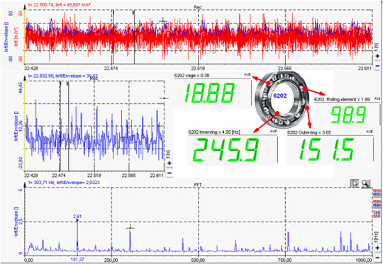
This was a simulated case to see the math procedure behind calculation. In reality the signal will look like this. Not much to see from the time signal, but with calculation of typical frequencies we can see that the outer ring frequency is clearly shown in the FFT of the envelope signal.
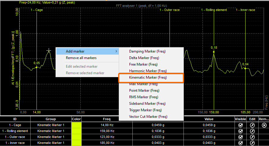
To add Kinematic marker on the spectrum, right click on it and select Add Kinematic marker.
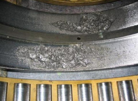
The following picture shows the typical damage of the outer ring of the large bearing (courtesy of Kalmer d.o.o. Trbovlje).
NOTE: Please note, that in order to use Kinematic marker, you need to have a valid license for FFT analyser or DSA license.