Real Measurement
In the Real measurement mode, we can see a list of connected devices and their settings.
Dewesoft devices (SIRIUS, SIRIUS-XHS, DEWE-43, KRYPTON, IOLITE, SBOX, ECAT-SYNC JUNCTION) connected over USB or ECAT are automatically recognized and added to the system overview.
Dewesoft network devices (SIRIUS-XHS, OBSIDIAN, IOLITE-X and SIRIUS-X) connected over Ethernet are automatically detected but need to be added to the HW list manually. Some other device plugins such as cameras, navigation devices (GPS, NAVION, etc..) also need to be added manually.
NOTE: Network devices may not be found automatically due to network restrictions. Please check all network and firewall rules.
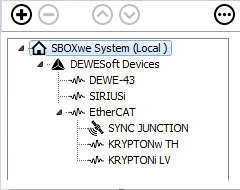
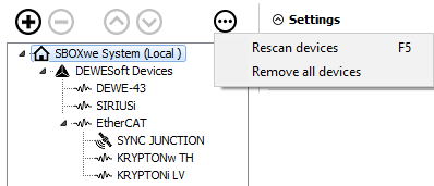
We can see the currently connected HW devices on the left side of the menu. In this example, we have the SBOX system with connected USB (SIRIUS, DEWE-43) and EtherCAT devices (KRYPTON, ECAT-SYNC JUNCTION).
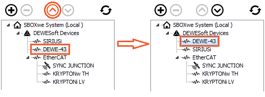
You can rearrange the order of the devices with the up and down buttons.
Adding New Network Device, Measurement Unit (Dewesoft NET) or Device Plugin
With the plus button, we add devices that are not added to the system automatically. We can remove them with the minus button.
When adding a new device, the following menu will appear:
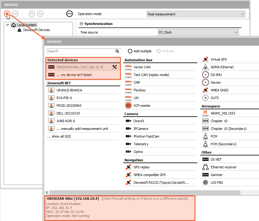
Under Detected devices, all network devices will be listed (SIRIUS-XHS, OBSIDIAN, X-line). At the bottom of the menu, you will see the important device information such as device name, IP address and location.
The devices will be detected, even if the IP address does not match the IP on the PC. From this menu, you can directly edit the network settings of the device ( configure IP address). If the device is in Operation mode and you want to change the IP address of the device, it will be stopped. If the device is not detected, please check your firewall settings.
NOTE:Operation mode means that the device is working as a standalone device and all device properties are locked.
Under Dewesoft NET, you will find measurement units that you can add to your system with more information at the bottom.
In this menu, you will also find other device plugins that you can add.
By enabling the Add multiple option at the top of the menu, you can add multiple different items from this menu to your system configuration at the same time.
On the right side of the window, the properties of devices are shown and some settings can also be changed.
Refresh or Remove All Devices
By clicking on the three-dot button, two additional options will apear: - scan the whole structure of a system again (shortcut - F5) - remove all devices from the list
SBOX System
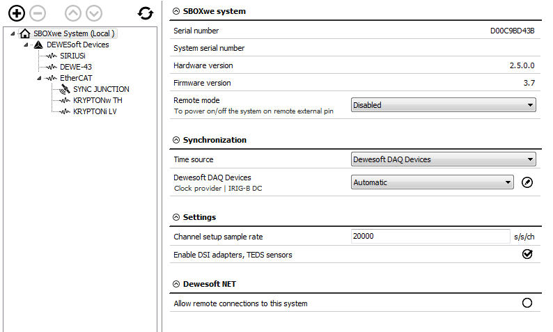
We can select SBOX from the list and see device information (serial number, hardware, and firmware version).
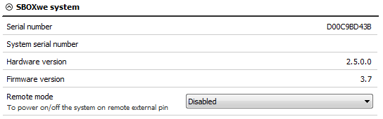
If the SBOX system is used, the remote mode can be used to turn the SBOX on or off remotely.
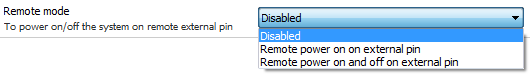
The SBOX power supply connector has three pins: voltage, ground connection, remote signal.
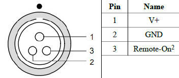
- Disabled - If remote mode is disabled, SBOX can only be turned on or off by pressing the power button on the device.
- Remote power ON on external pin - The SBOX can be remotely turned on with a signal to the remote pin.
- Remote power ON and OFF on external pin - The SBOX can be remotely turned on or off.
WARNING:After the Remote mode option is changed, a total reset of the device is required. The SBOX needs to be shut down and disconnected from the power supply. If the SBOX is powered by batteries (e.g. R1DB, R8B,..), then the batteries need to be removed as well.
SIRIUS
We can now see SIRIUS device information and settings by selecting it from the list.
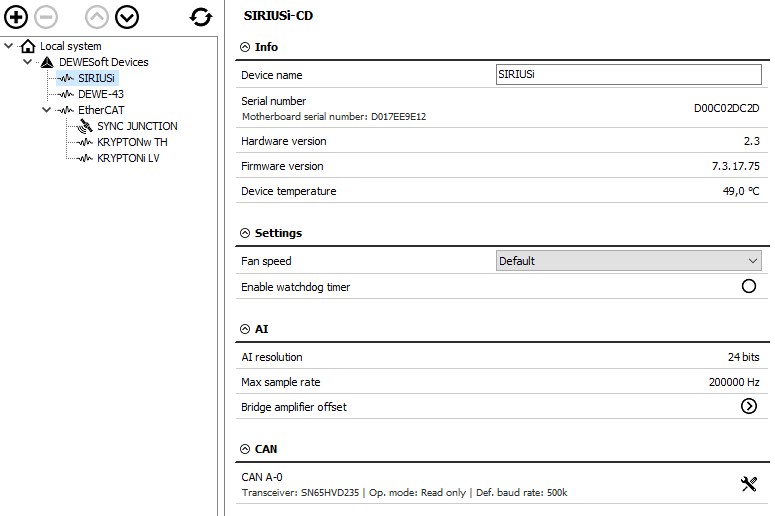
Bridge amplifier offset shows us the initial amplifier offset. Sirius connects the input shorted and the offset is measured.
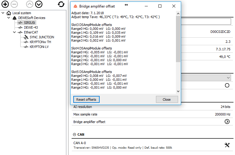
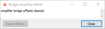
With the button Reset offsets, we clear the initial amplifier bridge offsets.
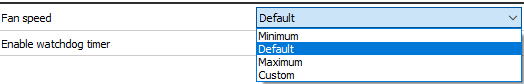
Fan speed can be set to default, minimum, maximum, or custom. Custom speed is defined as a percentage of the maximum fan speed.
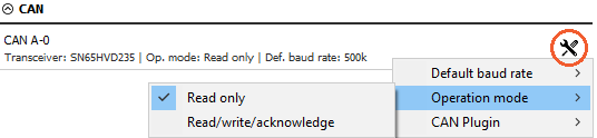
We can change the CAN baud rate and CAN operation mode (Read only or Read/Write/Acknowledge).
Watchdog Timer
NOTE:An extensive overview of the watchdog timer is in the Watchdog Manual.
Dewesoft is often used in many critical applications where the control system depends on the data acquisition system or the data acquisition system outputs alarms that warn the user or switch off the test. In such cases, it is important to know the operation state of the data acquisition system. Watchdog is a safety feature that switches on the digital output when the system is in operation, and switches off if the data acquisition system becomes unresponsive. A timeout can be set to delay switching off the watchdog. This feature can be used with any SIRIUS or IOLITE instrument with a Digital output.
NOTE: The watchdog can only be mapped to one digital output!
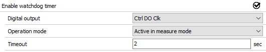
The timeout value specifies the time in which Dewesoft must reset the watchdog.
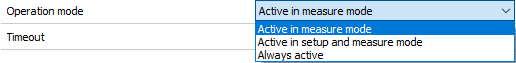
Operation mode can be selected from:
- Active in measure mode - The watchdog is active while Dewesoft is in measure mode.
- Active in setup and measure mode - The watchdog functionality is active while Dewesoft is in channel setup and in measure mode.
- Always active - The watchdog is always active.
Digital output menu selects on which digital output the watchdog functionality is enabled.
NOTE: The watchdog is not active while in Analyze mode!
When using a SIRIUS-8xSTGM+-DB device, a special watchdog module called DS-WDT can be connected via a D-sub 25 pin cable. It indicates the operation of the Watchdog timer with an LED light.
To learn more about the watchdog timer and the DS-WDT, read the Watchdog Manual.
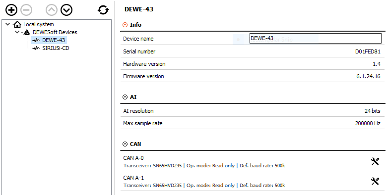
DEWE-43
In the DEWE-43 settings, we can change the CAN baud rate and CAN operation mode (Read only or Read/Write/Acknowledge). We can also see the name of the device, serial number, hardware version, and firmware version.
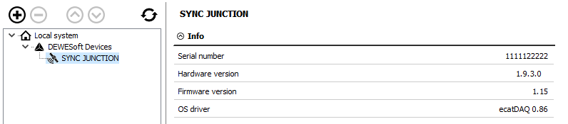
ECAT-SYNC JUNCTION
ECAT-SYNC JUNCTION works identically as other Dewesoft USB devices. It is automatically recognized within DewesoftX. By default, ECAT-SYNC JUNCTION will be set up to synchronize KRYPTON EtherCAT® and SIRIUS USB. The serial number and the firmware version can be seen and also updated.
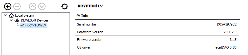
KRYPTON
For KRYPTON, serial number, hardware, and firmware versions are displayed. Also, the firmware upgrade can be done.
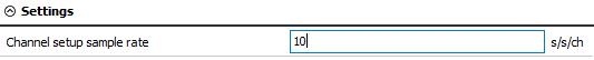
Channel Setup Sample Rate
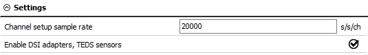
This field will allow you to set the channel setup sample rate, which is the number of samples per second per channel. Channel setup sample rate does not run with the full acquisition sample rate but with a reduced one.
NOTE:This only relates to SIRIUS devices. ECAT devices have a 1000 s/s/ch Channel setup sample rate by default, and this setting does not affect them.
The following example will illustrate why picking a sensible sample rate is one of the keys to obtaining coherent data:
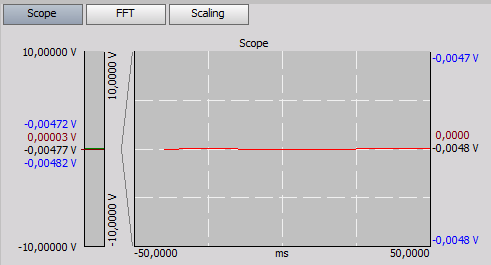
Let’s take a look at a signal from a function generator - simple sine wave of 100 Hz. First, we will let the channel setup sample rate at the default value, 20 000 s/s/ch.

When we enter the setup of the selected channel, we see the preview of the scope nicely.
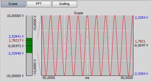
Now, we will change the channel setup sample rate to 10 s/s/ch.
The preview of the channel does not show the proper form of the signal, because it is sampled with a lower sample rate than it should be. The signal changes so much between two samples that we will not get a coherent readout.