PID control
Dewesoft can be used as a PID controller by using the PID Control.
WARNING: Dewesoft software running on Windows is not a real-time system because Windows is not a real-time operating system. This means that the delay of the controller is not always the same and can be unpredictable. For example Windows could give priority to another application instead of Dewesoft, which can dramatically increase controller delay.
When you press the Setup button on newly activated PID control line, the following setup screen window will open:
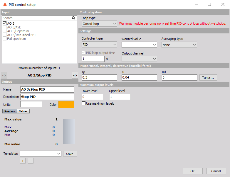
Control system
Loop type - if Open loop is chosen, there is no feedback to the controller. In measure mode, the user can set a value to the controlling channel (analog or digital output, for example) and measure the response without controller interference. This option is useful for obtaining the step response of the system. If Closed loop is chosen, the feedback loop is turned on and additional settings appear.
Settings
- Controller type - we can choose between a PID controller and a PI controller with anti-windup (anti-windup will be described later in this tutorial). If only the P controller is needed, the PID type can be chosen and zeros filled in for I and D gains.
- Wanted value - the set point. In the figure above we created a user input channel (under Channel Setup, User Inputs) called ‘Set point freq’in order to be able to change the setpoint during measurement.
- Output channel - the controller output. Normally an analog or digital output channel would be chosen. In the figure above we named the analog output channel as “Control AO voltage”.
- PID loop output time - the period at which the controller will update the Output channel.
- Averaging type - the method of averaging the error (error = wanted value - input). Can be used if there is a lot of noise in the process value.
Maximum output levels
Maximum output levels set the minimum and maximum levels of the Output channel and can be set if desired.
Integrator windup limit
Integrator windup limit is visible when Controller type is set to PI with anti-windup and sets the limits of the Output channel in its units. When the Output channel is outside this limits, the error will not be integrated. There is another way to conquer a large dead time. In the PID setup, we can choose the PI controller type. This will prevent the accumulation of the integration error when the actuator is in saturation, which happens during dead time. If this type of controller is chosen, the Ziegler-Nichols method provides very good response also in the case of a large dead time.
For additional help with PID Control visit Dewesoft PRO training ->Dewesoft Web page -> PRO Training -> PID Control.