Strain rosette
The rosettes mathematics plugin is used to calculate the plane strain and plane stress state, measured by strain gages in common strain rosette patterns. To learn more about the strain and stress measurement you can visit the Strain measurement PRO tutorial.
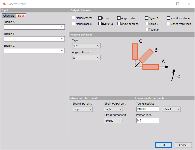
When you add the rosette mathematics in DEWESoft’s Math module, the following Rosette setup window will appear.

In the Rosettes setup you can define inputs from strain gages, calculation settings and desired strain and stress outputs. Settings that go together are grouped under panels:
Input
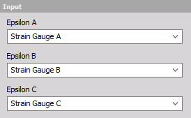
Here you can pick channels that define the strains of strain gages A, B and C of a strain rosette. Channels that can be used as inputs have to be synchronous, scalar and without a sample rate divider. In the special case of a 90° rosette, only Epsilon A and Epsilon B channels have to be defined for a sucessfull calculation. Otherwise all three inputs have to be defined.

Output channels
Here you can pick which channels are going to be the outputs of the Rosettes math. There are eleven strain and stress outputs available.
Strain outputs * Mohr’s center * Mohr’s radius * Epsilon 1 * Epsilon 2 * Angle radian * Angle degrees
Stress outputs * Sigma 1 * Sigma 2 * Tau max * von Mises stress * Signed von Mises stress
Strain outputs
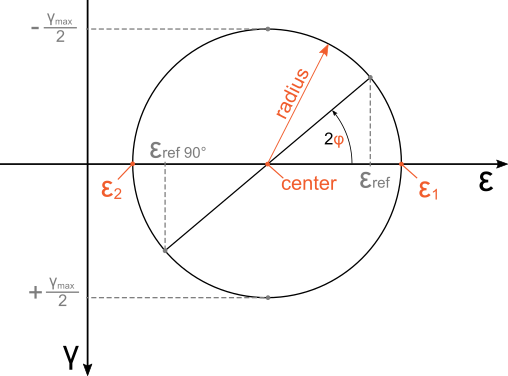
With the strain outputs you can get all the parameters needed to represent the two dimensional strain state in a Mohr’s circle.

The outputs that can be selected in the Rosettes are in orange.
- Mohr’s center: Represents the center of Mohr’s circle of strain.
- Mohr’s radius: Represents the radius of Mohr’s circle. Its magnitude is the same as half of the maximum engineering shear strain.
- Epsilon 1: Maximum principle normal strain in plane.
- Epsilon 2: Minimum principle normal strain in plane.
- Angle: This can be output in radians or degrees. It is the angle from the max principal strain direction to the direction of the strain gage that was picked as a reference in the rosette definition.
Stress outputs
Hook’s law is used to calculate the stresses from measured strains. Calculated stresses are valid for materials and loadings where relationship between strains and stresses are linear and equal in every direction of the measured plane. Young’s modulus and Poisson’s ratio that are needed for the transformation can be specified under the linear elastic parameters. Since the strains are only measured on the surface, stress outputs are valid only when the stress state can be regarded as planar. This is true when stresses perpendicular to the plane of measurement can be neglected in the analysis.
Stress outputs are:
- Sigma 1: Maximum principal normal stress in the plane.
- Sigma 2: Minimum principal normal stress in the plane.
- Tau max: Maximum shear stress in the plane.
- von Mises stress: Stress calculated according to von Mises’ yield criterion in two dimensions.
- Signed von Mises stress: The same magnitude as von Mises’ but the sign is negative in cases when the absolute value of the minimum principal normal stress Sigma 2 is greater than the absolute value of the maximum principal stress Sigma 1.
Output
In the output section you can see and modify channel properties of outputs that are activated in the Output channels section.
Rosette definition
To determine the two dimensional strains at least three normal strain measurements in different directions are needed. Rosettes offer four different rosette types to pick from: 45°, 60°, 120° and 90°. The first three (45°, 60°, 120°) calculate the strain state from three strain gages measurements. They can determine the full two dimensional strain state. The only difference between them is in the angle between strain gages. The 90° rosette is different as it only uses two strain gages measurements to calculate the outputs. The 90° rosette should only be used when the principal strain directions in the plane are aligned with its strain gages. Beacuse of this, outputs which aren’t relevant to a 90° rosette are automatically disabled.
- Rosette 45°: Three strain gages are angled at 45 degrees. Any of the strain gage directions can be picked as the angle reference direction.

- Rosette 60°: Three strain gages are angled at 60 degrees. Any of the strain gage directions can be picked as the angle reference direction.

- Rosette 120°: Three strain gages are angled at 120 degrees. Any of the strain gage directions can be picked as the angle reference direction.

- Rosette 90°: Two strain gages are angled at 90° degrees. The principal strain direction has to be parallel with strain gage directions to produce correct results (e.g. tenisle test). Only outputs: Epsilon 1, Epsilon 2, Sigma 1, Sigma 2, von Mises stress and Signed von Mises stress are available.

Strain and stress units
Rosettes offer automatic conversion of stress and strain units. Rosettes only use units available in the Physical Quantities Editor, where you can also define additional strain and stress units. Unit settings that can be dfined are:
Strain input unit: Here you can either pick the strain unit or allow the rosettes to determine the unit of input channels automatically. If you choose to pick the unit then the rosettes module will assume that all of the values of input channels are in this unit. If you pick the setting From inputs then the unit of the output channel is going to be determined based on the unit of the input channel. If this unit isn’t recognized as one of the strain units defined in the Physical Quantities Editor the value of the input channel is going to be regarded as dimensionless strain.
Strain output unit: All of the strain outputs are going to be in the unit that is selected here.
Stress output unit: All of the stress output are going to be in the unit that is selected here.
Linear elastic parameters
Here you can define the parameters of an isotropic linearly elastic material. These are used to calculate plane stress outputs from rosette strain measurements.
Young modulus: The elastic modulus of the material, defines the slope of the stress-strain curve in a linear elastic part material deformation. The modulus is defined in units of stress. You can specify the unit in which you want to define the Young’s modulus from one of the units of stress defined in the Physical Quantities Editor.
Poisson ratio: The negative ratio between axial and transverse strain. The ratio is dimensionless.
Default values are 210 000 N/mm^2 for Young modulus and 0.3 for Poisson ratio.