Trigger Setup
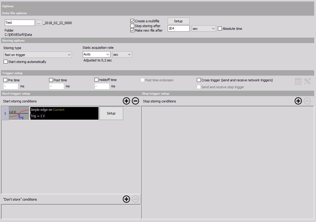
If you select one of the triggered storing options - Fast on trigger or Fast on trigger, slow otherwise, Trigger setup will appear below the already existing storing options. Triggered storing means that Dewesoft will wait for an event in a signal - a trigger to start storing.
Settings

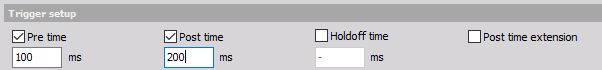
You can use the following timing setup options to set how long storing will be around the trigger event:
- Pre time - Duration of storage before the trigger event. Dewesoft will keep data in a buffer until the trigger event occurs and save the selected duration.
- Post time - Storage duration after the trigger event.
- Holdoff time - Minimum time between two trigger events for both to be stored.
- Post time extension - If more trigger events occur when the first one is still being recorded, acquisition will be prolonged.
The other two options in this section are related to Dewesoft NET:
- Cross trigger (send and receive network triggers)
- Send and receive stop trigger
Example:
If the Pre time is 100 ms, and the Post time is 200 ms, 300 ms of data in total will be captured per trigger event:
Conditions
You can set three types of trigger conditions:
- Start storing
- “Don’t store”
- Stop storing
NOTE: If you have both a Post time and a Stop storing condition set up, Dewesoft will dtop storing at whichever happens first: Post time elapses or a stop storing event happens.
Use the + and - buttons to add and remove triggers. When you add a trigger, click on the Setup button to modify it. The Condition setup window, identical for all three types of trigger conditions, will open:
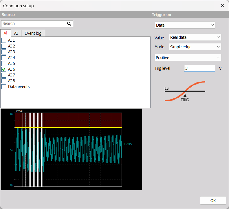
After choosing an input channel from the list on the left side, you can see its current readout below it. If you wish to select multiple condition sources, click and drag down the list or hold CTRL and click on the sources you want to select.
On the right side, choose what storing will trigger on and modify parameters.
Trigger On
Trigger events can be related to:
- Data
- Time
- FFT
Data Trigger
If triggering on data, you can modify:
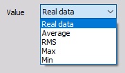
- Value - Real data, Average, RMS, Max and Min. The Average, RMS, Max and Min values are taken from the Static acqusition rate data.
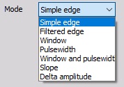
- Mode
- Simple edge - The trigger event is a rising or falling edge, which crosses a defined level.
- Filtered edge - Similar to Simple edge, but with a Rearm level. This value must be reached before the trigger event will be used for storing again. Useful for very noisy signals.
- Window - Define a range and trigger when the signal enters the range or leaves it.
- Pulsewidth - Choose if the pulse signal is crossing above or below the trigger level and if it has to stay there longer or shorter than a certain time period.
- Window and pulsewidth - Combines the two modes; the signal can be in or out of range for longer or shorter that the set time in order to cause a trigger event.
- Slope - The trigger event can happen when a signal’s Delta level is positive, negative, or both. You will also have to set if this difference in levels is smoother than (slower) or rougher than (faster) than the Delta time.
- Delta amplitude - Triggers if the amplitude difference is greater than the set value. The difference can be positive, negative, or both.
- Other settings - e.g. Slope, Trigger level, Rearm level, Pulse time…, depend on the selected Mode.
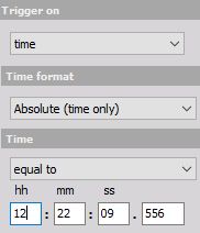
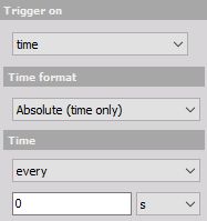
Time Trigger
You can choose between Relative time, i.e. time elapsed since start of measurement, or Absolute (time only). The trigger event can happen when a set amount of time has passed or trigger events can happen every __ seconds/minutes/hours.
FFT Trigger
Using an FFT trigger means that Dewesoft will react to trigger events in the frequency domain. This is useful in dynamic applications where you want to supervise the frequency behavior of the system.
NOTE: For more information on Fast Fourier Transform (FFT), please refer to our Guide.
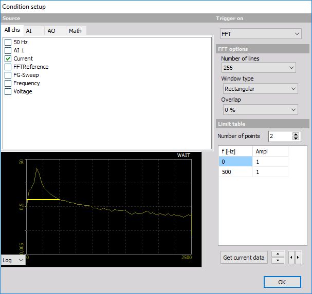
FFT options
The following options are available in the Setup window:
- Number of lines - 256 to 64k
- Window type - Rectangular, Hanning, Hamming, Flat Top, Triangle, Blackman, Exponent down
- Overlap - 0, 25, 50, 66 and 75%
For information about Number of lines, Window type and Overlap see —> FFT analyser
NOTE: Preview at the left bottom area shows the change effects on the FFT immediately. On this display can be select beside Logarithm (see display above) also Linear display.
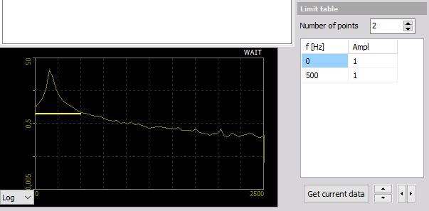
Limit Table
You can find the Limit table right below FFT options. In it, you can change:
- Number of points - number of limits
- f [Hz] and Amplitude of a limit
The default number of points is 2 (0 and 500 Hz) and the default amplitude for those two points is 1.
You can define limits in two ways:
- Enter values manually - Click on a box and type the value in.
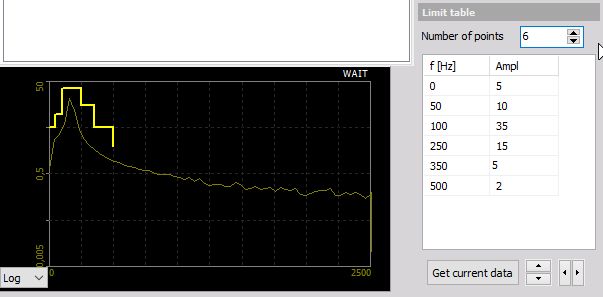
- Get current data - The currently calculated FFT will be stored as a mask and displayed on the preview display and in the table.
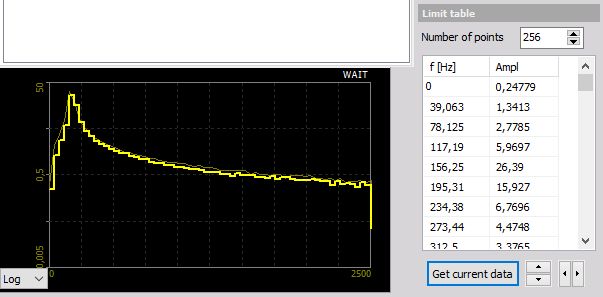
You can manipulate the mask by editing the table or press the up/down and left/right buttons.
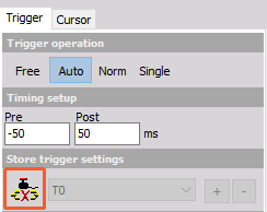
Scope Widget
When using the Scope widget, you can link its triggers and systems triggers. Any changes done in the Scope widget menu will be copied to the system and vice versa.