Scaling
The Scaling procedures define the ratio between the electrical input value of the selected input channel (from the amplifier) and the scaled physical-engineering input value, which is used in Dewesoft procedures.
The scaled “physical-engineering” input value is needed for signal display or to have different units as the “electrical” input value.
The bottom-right section of the Channel setup for channel n screen is where you can perform:
- Scaling - calibrating on input: either on a 2-point or functional basis
- manual/automated calibration
The bottom-right section of the dialog contains a dynamic representation (Live data preview) of your signal - the left side is the ‘electrical’ units, and the right side is the scaled ‘physical-engineering’ units, so you can directly see the effect of your calibration values.
Calibrating on input ‘by two points’
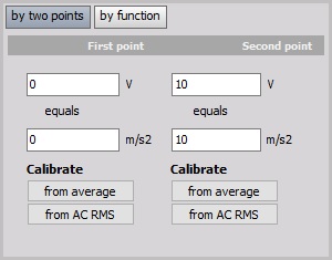
In this example we enter scaling factor so that the input channel on First point: 0 real volts equals 0 m/s2, and on Second point: 10 V (electrical units) equals 10 m/s2 (engineering units - Acceleration).
Please note that when changing one point, the scaling and offset changes as well. Therefore it is not good in the example above to ‘calibrate from average’ of the first point, because the scaling factor will change as well. Please look at the following section - Scaling by function and perform a sensor zero.
For additional help with scaling factor visit Dewesoft PRO training ->Dewesoft Web page -> PRO Training.
Calibrating on input ‘by function’
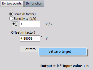
Another way to perform such a simple linear function would be to simply multiply the input by a factor. You can easily do this by clicking the by function button, which will change the two-point calibration portion of the dialog to look like this:
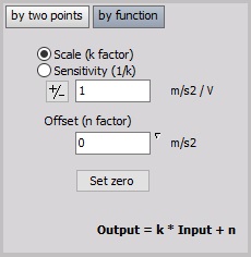
In the above example, we calibrate the system so that for channel this factor is 1.
Above shows your basic algebraic formula:
$$y = kx + n$$
- $y$ - physical value
- $k$ - scale
- $x$ - measured value
- $n$ - offset
for a general linear function, which makes it easy to input k factor and Offset (n-factor).
There are two ways of entering the value:
- Scale (k factor); example above: k = 1 m/s2 / V (Scale factor is the factor which defines how to scale the electrical signal to deduce the physical values).
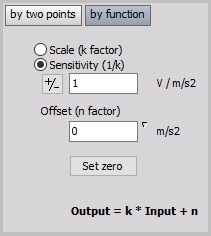
- Sensitivity; example on below: k = 1 V / m/s2 (Sensitivity is the factor which is usually used in sensor calibration sheets and defines the electrical output per physical quantity measured by the sensor.
Set Zero button is used in the main setup to conveniently offset the signal to ‘force’ it to zero, when it is not exactly at that value (but should be), due only to small sensor offsets and perhaps long cable lengths causing capacitive coupling and/or line loss.
Example:
An even easier way to convert from °C (Celsius) to °F (Fahrenheit) is to click by function, then enter the $y=kx+n$, to perform simple offset.
By multiplying °C by 1.8 as Scale and then adding 32 as an Offset, the same result is achieved.
Since modules that measure temperature output their values in the scientific standard Celsius scale, this is a handy formula to know when the temperature is desired in Fahrenheit.
For useful hints about scale (k factor) and Sensitivity by different Measurement applications see ->Dewesoft Web page -> PRO Training.
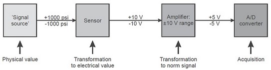
Calibrating on input example
Pressure up to ±1000 psi (= signal source) will be measured with a 100 psi / V sensor, connected to a high voltage module (= amplifier with 10V range).
In the example screen, you can see that the default values are entered - the real and engineering units are the same. But what if this was a pressure sensor that had a voltage output and each volt represented 100 psi of pressure?
Scaling ‘by two point’
Here is how we would set it up - starting at the top; we enter our text values for this channel. Then in the bottom-left, we tell the system that 0 real Volt equals 0 psi, and 1 real Volt equals 100 psi. If you look at the graph on the bottom-right corner of the dialog, you can see that the real input signal has a min of 0.01466 V at this moment, which is being scaled to 1.466 psi, which is exactly what you would expect.
Scaling ‘by function’
Another way to perform such a simple linear function would be to simply multiply the input by a factor of 100. You can easily do this by clicking the by function button, which will change the two-point calibration portion of the dialog.
There are two ways of entering the value (just a question of the value):
- Scale (k factor); example above: k = 100 psi / V
- Sensitivity; same example: k = 0.01 V / psi
Both methods can cause a small offset. Use the Set Zero button in the main setup to conveniently offset the signal to force it to zero.
Scaling ‘by function’ to a non-zero target
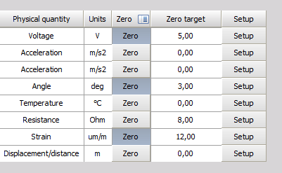
If the sensor you are trying to calibrate has a defined Scale or Senstitivity, but can’t be set to its zero position, you can also determine its offset if the sensor is set to known non-zero value. You can define the target calibration value by righ-clicking on the Set zero button and entering the desired value. The action will only configure the target but will not set the offset. This is done when the Set zero button is pressed.
Additionaly, you can also add the Zero target column in the analog grid to edit the zero target directly in channel setup.