IIR Filter setup
When you press the Setup button on new activated IIR Filter line, the following IIR Filter setup window will open:
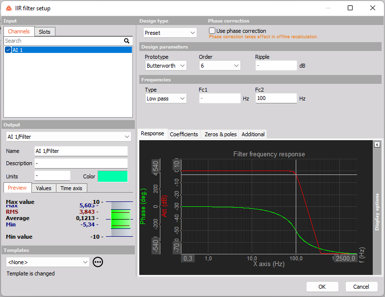
The filter supports multiple input channels.
For detailed information about basic settings of the input and output channels see -> Setup screen and basic operation.
IIR is the abbreviation for infinite impulse response. It means that the response to the impulse will be non zero over an infinite length of time. The calculation behind is that the new filtered value is calculated from the current and previous input values as well as previous output values.
That’s the theory. In practice, we can say that the IIR filter is a direct equivalent to the RC type’s analog filters.
For example we can achieve the exact theoretical low pass, high pass, sound weighting and other standard filters which were achieved by analog circuits in classic ‘old school’ instruments.
NOTE: For accurate offline post-processing or recalculations, it is essential to store all relevant data channels from the beginning of the measurement. Missing raw data channels will prevent the system from properly utilizing the history required for precise recalculation.
Design type
First, with Design type you can select if the IIR filter should be a Preset (commonly known) type of filter, or if it should be a manually configured filter.
Preset IIR filters
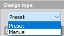
If you select Preset then you can setup the filter using the parameters under the sections Design parameters and Frequencies, as shown below:
Design parameters
Using the design parameters you can configure the overall definition of the filter within the limitations of the preset filter types.
Prototype
 Select between Butterworth, Chebyshev I and Bessel filter types. Bessel filters have a maximally flat group-delay characteristic and hereby Bessel filters have the most flat phase response. Butterworth filters have a maximally flat magnitude response characteristic. Chebyshev filters, on the other hand, have an equiripple magnitude response characteristic in the pass-band as a consequence of providing a shaper/steeper cut-off slope.
Order
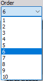 Select the order of the preset IIR filter. Increasing the order will also increase the steepness of the cut-off slope
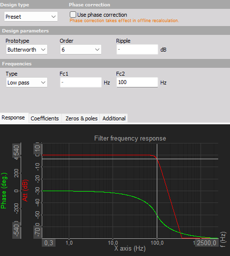
Ripple This is only applicable for the Chebyshev filtertype. The Ripple parameter sets a limitation of the equiripple on pass-band. With an increaed Ripple value you can achive a sharper cut-off slope, but you will get the increased ripple characteristic in the pass-band.
Frequencies
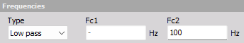
Using the Frequencies parameters you can determine the shape of the filter and hereby define which frequencies that should be included and excluded in the filtered output signals.
Type
 Select how the filter should handle/filter signals when seen from the frequency domain.
Low pass will include frequency components below the user-defined Fc2 frequency value, and exclude the frequency components above Fc2.
High pass will exclude frequency components below the user-defined Fc1 frequency value, and include the frequency components above Fc1.
Band pass will include frequency components in the band between the user-defined Fc1 and Fc2 frequency values, and exclude the frequency components outside that frequency band.
Band stop will exclude frequency components in the band between the user-defined Fc1 and Fc2 frequency values, and include the frequency components outside that frequency band.
Manual IIR filters
If you select Manual then you will be able to configure the filter manually by writing the coefficient values for all filter sections in a table like illustrated below:
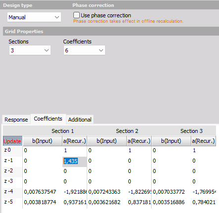
In the coefficient table you see columns of a(Recur.) and b(Input) for each filter section. a(k) and b(k) are the IIR filter denominator and numerator polynomial coefficients who’s roots are equal to the poles and zeros of the filter respectively.
Grid properties
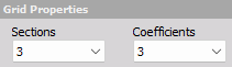
With the Grid properties you can setup and define the filter characteristics in multiple ways:
Sections - let you define the number of filter sections the overall filter should have. By using multiple sections you can e.g. create a high order filter out of multiple second order biquad filter sections.
Coefficients - let you define the feedforward filter order and the feedback filter order of all the filter sections. By increasing the number of coefficients you can increase the filter order without increasing the number of sections.
Phase correction
IIR filters will affect the phase response of the input signals. If the filtering should only affect the magnitude shape and let the phase characteristic stay the same, then check on the ‘Use phase correction’.
By enabling the phase correction a two-pass filtering will be used - one forward and one backward. This will effectively give the desired magnitude filtering while cancelling out the phase change from the filter.
NOTE: Phase correction will only be applied in post-processing, also referred to as Offline or Analyze mode, where you can recalculate the filtering.